Use and Care Guide
Page 1
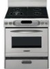
...appareil. GAS RANGE Use & Care Guide For questions about features, operation/performance, parts accessories or service, call: 1-800-422-1230 In Canada, call for assistance 1-800-461-5681, for future reference. Pour le consommateur: lire ce manuel et le conserver pour consultation ultérieure. www.KitchenAid.ca..., call: 1-800-807-6777 or visit our website at... Models/Modèles KGRI801 KGRA806 KGRK806 KGSI901 KGSA906 9757452 www.kitchenaid.com or www.KitchenAid.ca CUISINIÈRE À GAZ Guide d'utilisation et d'entretien Au Canada, pour assistance composez le 1-800-461-5681,...
...appareil. GAS RANGE Use & Care Guide For questions about features, operation/performance, parts accessories or service, call: 1-800-422-1230 In Canada, call for assistance 1-800-461-5681, for future reference. Pour le consommateur: lire ce manuel et le conserver pour consultation ultérieure. www.KitchenAid.ca..., call: 1-800-807-6777 or visit our website at... Models/Modèles KGRI801 KGRA806 KGRK806 KGSI901 KGSA906 9757452 www.kitchenaid.com or www.KitchenAid.ca CUISINIÈRE À GAZ Guide d'utilisation et d'entretien Au Canada, pour assistance composez le 1-800-461-5681,...
Use and Care Guide
Page 5
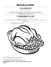
...500 BTU) 5 The locations and appearances of the features shown here may have some or all of your model. Surface burner locator B. PARTS AND FEATURES This manual covers several different models. Right front control knob (6000 BTU) G. Right rear control knob (12,500 BTU) 325...BTU) E. Oven display C. Right front control knob (6000 BTU) G. Control Panel for Standard Burner (Models KGRI801 and KGSI901) A B F G F. The range you have purchased may not match those of the items listed. Oven control panel Control Panel for TripleTier™ Burner (Models KGRA806, KGRK806 and KGSA906...
...500 BTU) 5 The locations and appearances of the features shown here may have some or all of your model. Surface burner locator B. PARTS AND FEATURES This manual covers several different models. Right front control knob (6000 BTU) G. Right rear control knob (12,500 BTU) 325...BTU) E. Oven display C. Right front control knob (6000 BTU) G. Control Panel for Standard Burner (Models KGRI801 and KGSI901) A B F G F. The range you have purchased may not match those of the items listed. Oven control panel Control Panel for TripleTier™ Burner (Models KGRA806, KGRK806 and KGSA906...
Use and Care Guide
Page 6
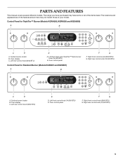
... surface burner & grate I 7 DI J K L C M D E A. Storage drawer F. Right rear surface burner & grate H. Model and serial number (behind left side of drawer) E. Bake burner & cover (not shown) Parts and Features not shown (on some models) Oven door window Broiler pan and grid Temperature probe T.H.E.™ convection fan & element Bakeware accessories Half rack with...
... surface burner & grate I 7 DI J K L C M D E A. Storage drawer F. Right rear surface burner & grate H. Model and serial number (behind left side of drawer) E. Bake burner & cover (not shown) Parts and Features not shown (on some models) Oven door window Broiler pan and grid Temperature probe T.H.E.™ convection fan & element Bakeware accessories Half rack with...
Use and Care Guide
Page 19
... broiling, see "Broil" section for frozen foods. Press CONVECT BROIL. The convection broil range can be actively cooking. Press OFF when finished cooking. When the Sabbath Mode is ideal...CONVECT FULL MEAL. 3. "SABBATH ENABLED" will appear on the oven display until turned off after 30 seconds. Position rack. A single pad includes an oven setting, an oven temperature, and a ...be adjusted. Use the following chart as thinner cuts of the Sabbath. s Always check for only part of meat; Open the oven door. 2. COOK TIME or PROBE TEMP. Baked Salmon Steaks, ...
... broiling, see "Broil" section for frozen foods. Press CONVECT BROIL. The convection broil range can be actively cooking. Press OFF when finished cooking. When the Sabbath Mode is ideal...CONVECT FULL MEAL. 3. "SABBATH ENABLED" will appear on the oven display until turned off after 30 seconds. Position rack. A single pad includes an oven setting, an oven temperature, and a ...be adjusted. Use the following chart as thinner cuts of the Sabbath. s Always check for only part of meat; Open the oven door. 2. COOK TIME or PROBE TEMP. Baked Salmon Steaks, ...

Use and Care Guide
Page 26
... prompts. To locate the KitchenAid designated service company in the United States. Saturday 8:30 a.m. - 4:30 p.m. (EST). ASSISTANCE OR SERVICE Before calling for assistance or service, please check "Troubleshooting." Accessories U.S.A. s Installation information. Stainless Steel Cleaner & Polish (stainless steel models) Order Part #4396095 Gas Grate/Drip Pan Cleaner Order Part #31617 Griddle Accessory Order Part #4396096 Brick Pizza Stone...
... prompts. To locate the KitchenAid designated service company in the United States. Saturday 8:30 a.m. - 4:30 p.m. (EST). ASSISTANCE OR SERVICE Before calling for assistance or service, please check "Troubleshooting." Accessories U.S.A. s Installation information. Stainless Steel Cleaner & Polish (stainless steel models) Order Part #4396095 Gas Grate/Drip Pan Cleaner Order Part #31617 Griddle Accessory Order Part #4396096 Brick Pizza Stone...
Use and Care Guide
Page 27
On gas ranges and gas cooktops, in the second through fifth years from the date of purchase, when this appliance is operated and maintained according to instructions attached to or furnished with the product, KitchenAid will pay for factory specified parts for the porcelain oven cavity/inner door if the part rusts through due to defects in...
On gas ranges and gas cooktops, in the second through fifth years from the date of purchase, when this appliance is operated and maintained according to instructions attached to or furnished with the product, KitchenAid will pay for factory specified parts for the porcelain oven cavity/inner door if the part rusts through due to defects in...
Installation Instructions
Page 2
... ...4 Tools and Parts ...4 Location Requirements ...4 Electrical Requirements ...6 Gas Supply Requirements ...6 Countertop Preparation ...7 INSTALLATION INSTRUCTIONS ...8 Unpack Range...8 Install Anti-Tip Bracket...8 Install Rear Vent ...9 Verify Anti-Tip Bracket Location ...9 Level Range...9 Make Gas Connection ...9 Check Operation ...10 Replace Oven Racks & Storage or Warming Drawer...12 Complete Installation ...12 GAS CONVERSIONS...13 LP Gas Conversion ...13 Natural Gas Conversion...15...
... ...4 Tools and Parts ...4 Location Requirements ...4 Electrical Requirements ...6 Gas Supply Requirements ...6 Countertop Preparation ...7 INSTALLATION INSTRUCTIONS ...8 Unpack Range...8 Install Anti-Tip Bracket...8 Install Rear Vent ...9 Verify Anti-Tip Bracket Location ...9 Level Range...9 Make Gas Connection ...9 Check Operation ...10 Replace Oven Racks & Storage or Warming Drawer...12 Complete Installation ...12 GAS CONVERSIONS...13 LP Gas Conversion ...13 Natural Gas Conversion...15...
Installation Instructions
Page 4
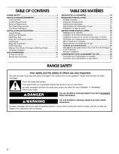
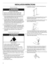
INSTALLATION REQUIREMENTS Tools and Parts Gather the required tools and parts before starting installation. Do not obstruct flow of combustion and ventilation air. Location Requirements IMPORTANT: Observe all governing codes and ordinances. Read and follow the instructions provided with any tools listed here.
INSTALLATION REQUIREMENTS Tools and Parts Gather the required tools and parts before starting installation. Do not obstruct flow of combustion and ventilation air. Location Requirements IMPORTANT: Observe all governing codes and ordinances. Read and follow the instructions provided with any tools listed here.
Installation Instructions
Page 8
... best procedure for final electrical connection. Remove template from range. Before moving range, slide range onto shipping base, cardboard or hardboard. 1. Remove oven racks and parts package from the carton. Place them lengthwise on the floor behind the range to remove. 4. Leveling legs can tip the range and be centered in front of 5.0 mm) is moved...
... best procedure for final electrical connection. Remove template from range. Before moving range, slide range onto shipping base, cardboard or hardboard. 1. Remove oven racks and parts package from the carton. Place them lengthwise on the floor behind the range to remove. 4. Leveling legs can tip the range and be centered in front of 5.0 mm) is moved...
Installation Instructions
Page 10
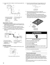
...oven burners use an extension cord. Nipple D. Manual gas shutoff valve G. ½" or ¾" gas pipe H. Remove cooktop burner caps and grates from parts package. Use a combination wrench and pliers to attach the flexible connector to the gas shutoff valve. Adapter (must have ½" male... Bubbles will not light. Check that connector is in burner caps with LP gas to the range. 2. Using a pipe wrench to tighten, connect the gas supply to the smaller thread ends of standing pilots. Union E. Gas pressure regulator B. 90° elbow (must have ½" male pipe thread...
...oven burners use an extension cord. Nipple D. Manual gas shutoff valve G. ½" or ¾" gas pipe H. Remove cooktop burner caps and grates from parts package. Use a combination wrench and pliers to attach the flexible connector to the gas shutoff valve. Adapter (must have ½" male... Bubbles will not light. Check that connector is in burner caps with LP gas to the range. 2. Using a pipe wrench to tighten, connect the gas supply to the smaller thread ends of standing pilots. Union E. Gas pressure regulator B. 90° elbow (must have ½" male pipe thread...
Installation Instructions
Page 12
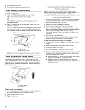
...all of liquid household cleaner and warm water to light. Turn on your tools. 3. If range does not operate, check the following: 4. Close the oven door. 2. Check that the range is an extra part, go back through the steps to close drawer. Press the START pad. On some models..., "HEAT" and "ON" indicators will appear in the temperature display. 3. See "Level Range." 5. For more information, see which step was skipped....
...all of liquid household cleaner and warm water to light. Turn on your tools. 3. If range does not operate, check the following: 4. Close the oven door. 2. Check that the range is an extra part, go back through the steps to close drawer. Press the START pad. On some models..., "HEAT" and "ON" indicators will appear in the temperature display. 3. See "Level Range." 5. For more information, see which step was skipped....
Installation Instructions
Page 14
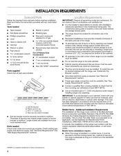
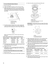
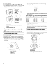
...a 7 mm nut driver to the following chart for correct LP gas orifice spud placement. Refer to help hold the gas orifice spud in the hex area. Remove burner cap. 2. Place Natural gas orifice spuds in plastic parts bag for future use and keep with 1 color dot, and have... mm A. Replace each Natural gas orifice spud with the correct LP gas orifice spud. Burner heads C. IMPORTANT: The three flame burner has 2 gas orifice spuds. External gas orifice spud C. Use a 7 mm combination wrench to help hold the internal gas orifice spud in plastic parts bag for the three flame burner...
...a 7 mm nut driver to the following chart for correct LP gas orifice spud placement. Refer to help hold the gas orifice spud in the hex area. Remove burner cap. 2. Place Natural gas orifice spuds in plastic parts bag for future use and keep with 1 color dot, and have... mm A. Replace each Natural gas orifice spud with the correct LP gas orifice spud. Burner heads C. IMPORTANT: The three flame burner has 2 gas orifice spuds. External gas orifice spud C. Use a 7 mm combination wrench to help hold the internal gas orifice spud in plastic parts bag for the three flame burner...
Installation Instructions
Page 16
...Surface Burners 1. A A A. Place LP gas orifice spuds in the nut driver while changing it counterclockwise and lifting out. Stamped number Refer to help hold the gas orifice spud in plastic parts bag for the correct Natural gas orifice spud placement. Washer E. Apply masking ...tape to remove. XXX Gas pressure regulator 4. Replace the LP gas orifice spud with a wrench to the end of gas pressure regulator) counterclockwise with the correct Natural gas ...
...Surface Burners 1. A A A. Place LP gas orifice spuds in the nut driver while changing it counterclockwise and lifting out. Stamped number Refer to help hold the gas orifice spud in plastic parts bag for the correct Natural gas orifice spud placement. Washer E. Apply masking ...tape to remove. XXX Gas pressure regulator 4. Replace the LP gas orifice spud with a wrench to the end of gas pressure regulator) counterclockwise with the correct Natural gas ...
Installation Instructions
Page 17
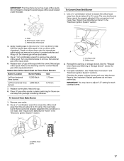
... Use a ½" combination wrench to loosen the orifice hood away from the pin (about 2 to help hold the internal gas orifice spud in plastic parts bag for instructions. 3. Internal gas orifice spud 4. Apply masking tape to the end of a 7 mm nut driver to 2½ turns). Set external... gas orifice spud aside. 6. Reinstall the warming or storage drawer. See the "Replace Oven Racks and Warming or Storage...
... Use a ½" combination wrench to loosen the orifice hood away from the pin (about 2 to help hold the internal gas orifice spud in plastic parts bag for instructions. 3. Internal gas orifice spud 4. Apply masking tape to the end of a 7 mm nut driver to 2½ turns). Set external... gas orifice spud aside. 6. Reinstall the warming or storage drawer. See the "Replace Oven Racks and Warming or Storage...


