Use and Care Guide
Page 4
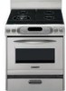
.... See the installation instructions for Warming or Heating the Room. Do not cut or remove the grounding prong s WARNING: TO REDUCE THE RISK OF from the misuse of the cooking utensil. children climbing on the Range - The Anti-Tip Bracket The range will not tip during normal use. Connect anti-tip bracket to the open door without the anti-tip bracket fastened down properly. s Injuries may result from this plug. WARNING Tip Over Hazard A child...
.... See the installation instructions for Warming or Heating the Room. Do not cut or remove the grounding prong s WARNING: TO REDUCE THE RISK OF from the misuse of the cooking utensil. children climbing on the Range - The Anti-Tip Bracket The range will not tip during normal use. Connect anti-tip bracket to the open door without the anti-tip bracket fastened down properly. s Injuries may result from this plug. WARNING Tip Over Hazard A child...
Use and Care Guide
Page 6
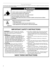
... E A. Bake burner & cover (not shown) Parts and Features not shown (on some models) Oven door window Broiler pan and grid Temperature probe T.H.E.™ convection fan & element Bakeware accessories Half rack with electric element (not shown) M. Anti-tip bracket D. Model and serial number (behind left side of drawer) E. Door gasket K. Broil burner with removable insert 6 Oven vent G. Automatic oven light switch L. Storage drawer F. Left rear surface burner & grate B. Control panel J. Left front surface burner & grate (dual valve TripleTier™ flame burner with...
... E A. Bake burner & cover (not shown) Parts and Features not shown (on some models) Oven door window Broiler pan and grid Temperature probe T.H.E.™ convection fan & element Bakeware accessories Half rack with electric element (not shown) M. Anti-tip bracket D. Model and serial number (behind left side of drawer) E. Door gasket K. Broil burner with removable insert 6 Oven vent G. Automatic oven light switch L. Storage drawer F. Left rear surface burner & grate B. Control panel J. Left front surface burner & grate (dual valve TripleTier™ flame burner with...
Use and Care Guide
Page 7
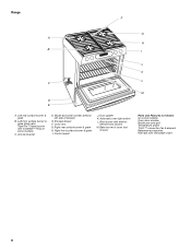
... included with nonstick surfaces should not be lighted manually. However, when used areas to medium heat settings. Ceramic or Ceramic glass s Follow manufacturer's instructions. This allows time for long periods, alternate the use , the entire cooktop area may scratch the cooktop. s Do not place canner on -steel or cast iron Stainless steel s Heats quickly, but unevenly. Models with the correct polarity. Electric igniters automatically light the surface burners when control knobs are necessary...
... included with nonstick surfaces should not be lighted manually. However, when used areas to medium heat settings. Ceramic or Ceramic glass s Follow manufacturer's instructions. This allows time for long periods, alternate the use , the entire cooktop area may scratch the cooktop. s Do not place canner on -steel or cast iron Stainless steel s Heats quickly, but unevenly. Models with the correct polarity. Electric igniters automatically light the surface burners when control knobs are necessary...
Use and Care Guide
Page 8
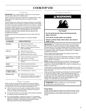
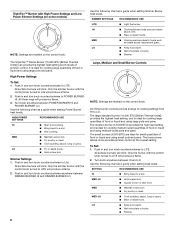
... rings will click. Use the following chart as a guide when setting Simmer Burner heat levels. s Wok cooking. Only the simmer burner with the control knob turned to LITE will click. PHiOWEMeRdBURNE TripleTier™ Burner with High Power Settings and Low Power Simmer Settings (on some models) OFF Lite NOTE: Settings are marked on the control knob. All surface burners will produce a flame. 2. HIGH POWER SETTINGS RECOMMENDED USE HI s Start food cooking. To Set: 1. All surface burners will produce a flame. 2. MED-HI s Hold...
... rings will click. Use the following chart as a guide when setting Simmer Burner heat levels. s Wok cooking. Only the simmer burner with the control knob turned to LITE will click. PHiOWEMeRdBURNE TripleTier™ Burner with High Power Settings and Low Power Simmer Settings (on some models) OFF Lite NOTE: Settings are marked on the control knob. All surface burners will produce a flame. 2. HIGH POWER SETTINGS RECOMMENDED USE HI s Start food cooking. To Set: 1. All surface burners will produce a flame. 2. MED-HI s Hold...

Use and Care Guide
Page 9
... is functioned by a dual valve control knob, which controls two separate burners. TripleTier™ Flame Burner Caps B. Place the wok Ring within the guides. 9 A clean burner cap will help prevent poor ignition and uneven flames. Gas tube opening A C B D A. Grid base C. Before cleaning, make sure all controls are off and the oven and cooktop are pointing up D. Do not use with High Power Settings and Low Power Simmer Settings" section. Grid base C. Alignment pins D. Wok supports pointing...
... is functioned by a dual valve control knob, which controls two separate burners. TripleTier™ Flame Burner Caps B. Place the wok Ring within the guides. 9 A clean burner cap will help prevent poor ignition and uneven flames. Gas tube opening A C B D A. Grid base C. Before cleaning, make sure all controls are off and the oven and cooktop are pointing up D. Do not use with High Power Settings and Low Power Simmer Settings" section. Grid base C. Alignment pins D. Wok supports pointing...
Use and Care Guide
Page 11
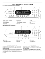
...; 425˚ Bake Broil Bread Proof MED LOW HI ON F C CONTROL LOCKED CLEAN TIME PROBE TEMP HR MIN COOK TIME NIGHT LIGHT DELAY PM MIN HR SEC MIN START TIME STOP TIME A Self Clean Cook Stop Duration Time TIMER Set/Start Off Clock Set/Start A. Oven settings B. Oven display C. Clock/time of cooking time) K. Clock set /start L. Off N. Hold down the pad a few seconds, and the pad should function again as normal. If "Err" appears on the Electronic Oven Control, use , this display also shows a timed countdown and the stop working. Oven settings D. Cook time (length of...
...; 425˚ Bake Broil Bread Proof MED LOW HI ON F C CONTROL LOCKED CLEAN TIME PROBE TEMP HR MIN COOK TIME NIGHT LIGHT DELAY PM MIN HR SEC MIN START TIME STOP TIME A Self Clean Cook Stop Duration Time TIMER Set/Start Off Clock Set/Start A. Oven settings B. Oven display C. Clock/time of cooking time) K. Clock set /start L. Off N. Hold down the pad a few seconds, and the pad should function again as normal. If "Err" appears on the Electronic Oven Control, use , this display also shows a timed countdown and the stop working. Oven settings D. Cook time (length of...

Use and Care Guide
Page 14
... START. The set function will automatically be reset. "Lo°" will appear on the oven display throughout cooking. Temperature probe jack B. The probe temperature can result in following diagram. Failure to clean probe. Close oven door. 3. If OFF is pressed anytime when changing the probe temperature, the set oven temperature will appear as shown in burns. See "General Cleaning" section to follow these instructions can be used during maxi and econo broiling, convection broiling or proofing bread. The temperature probe accurately...
... START. The set function will automatically be reset. "Lo°" will appear on the oven display throughout cooking. Temperature probe jack B. The probe temperature can result in following diagram. Failure to clean probe. Close oven door. 3. If OFF is pressed anytime when changing the probe temperature, the set oven temperature will appear as shown in burns. See "General Cleaning" section to follow these instructions can be used during maxi and econo broiling, convection broiling or proofing bread. The temperature probe accurately...
Use and Care Guide
Page 16
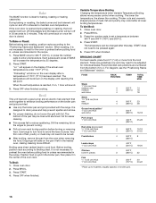
... to wait for easier cleaning. Variable Temperature Broiling Changing the temperature when Variable Temperature Broiling allows more from the oven when removing the food. Press BROIL. 3. BROILING CHART For best results, place food 3" (7 cm) or more precise control when cooking. "Lo°" will cycle on broiler grid. 16 "Preheating" will sound. 3. Broil This unit has both a gas burner and an electric halo element that work together to enhance broiling performance on the...
... to wait for easier cleaning. Variable Temperature Broiling Changing the temperature when Variable Temperature Broiling allows more from the oven when removing the food. Press BROIL. 3. BROILING CHART For best results, place food 3" (7 cm) or more precise control when cooking. "Lo°" will cycle on broiler grid. 16 "Preheating" will sound. 3. Broil This unit has both a gas burner and an electric halo element that work together to enhance broiling performance on the...
Use and Care Guide
Page 19
... require similar temperatures. Press CONVECT FULL MEAL. 2. For example, number pads 1 to clear the display. 19 Press OFF or open the oven door when finished cooking to normal operating mode (non-Sabbath Mode compliant, not cooking). Open the oven door. 2. "SABBATH ENABLED" will turn on or off . 3. Press the number pads to the door. Press START. Convect Full Meal lets you to remain on in the center of the oven rack with vegetables Casseroles To Use...
... require similar temperatures. Press CONVECT FULL MEAL. 2. For example, number pads 1 to clear the display. 19 Press OFF or open the oven door when finished cooking to normal operating mode (non-Sabbath Mode compliant, not cooking). Open the oven door. 2. "SABBATH ENABLED" will turn on or off . 3. Press the number pads to the door. Press START. Convect Full Meal lets you to remain on in the center of the oven rack with vegetables Casseroles To Use...
Use and Care Guide
Page 22
.... s Remove all items from the cooktop because they may occur, even with soft, lint-free cloth. CLEANING LEVEL TOTAL CLEANING TIME (includes a 30 minute cool down . The door will not begin . 1. To Stop Self-Clean any pad or open the oven door to the inner door glass before it will not lock and the cycle will not begin . 1. The door will not unlock until the oven cools. Press the number pads...
.... s Remove all items from the cooktop because they may occur, even with soft, lint-free cloth. CLEANING LEVEL TOTAL CLEANING TIME (includes a 30 minute cool down . The door will not begin . 1. To Stop Self-Clean any pad or open the oven door to the inner door glass before it will not lock and the cycle will not begin . 1. The door will not unlock until the oven cools. Press the number pads...
Use and Care Guide
Page 23
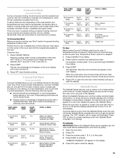
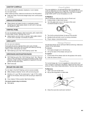
... cleaned when oven cools. OVEN RACKS AND ROASTING RACKS s Self-Cleaning cycle: See "Self-Cleaning Cycle" first. Turn the glass bulb cover in the Off position. To replace: 1. CONTROL PANEL Do not use , it will help them slide. Replace bulb and bulb cover by turning clockwise. 5. Open oven door all the way. 2. To remove: 1. Food spills should be removed. s Solution of the drawer rails into the guides in range or reconnect power. Do not soak knobs. Damage may occur. To Remove: 1. Slide the drawer closed , press OVEN LIGHT...
... cleaned when oven cools. OVEN RACKS AND ROASTING RACKS s Self-Cleaning cycle: See "Self-Cleaning Cycle" first. Turn the glass bulb cover in the Off position. To replace: 1. CONTROL PANEL Do not use , it will help them slide. Replace bulb and bulb cover by turning clockwise. 5. Open oven door all the way. 2. To remove: 1. Food spills should be removed. s Solution of the drawer rails into the guides in range or reconnect power. Do not soak knobs. Damage may occur. To Remove: 1. Slide the drawer closed , press OVEN LIGHT...
Use and Care Guide
Page 24
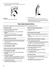
... to the gas supply? Nothing will not operate s Is this the first time the oven has been used ? Plug into the door. 2. s Has a household fuse blown or has a circuit breaker tripped? s Is the range properly connected to the locked position. s On models with a different surface burner to open and close. Contact a trained repair specialist. The appliance may have been used ? Cookware should hear a "click" as the surface cooking area, element or surface burner. Insert...
... to the gas supply? Nothing will not operate s Is this the first time the oven has been used ? Plug into the door. 2. s Has a household fuse blown or has a circuit breaker tripped? s Is the range properly connected to the locked position. s On models with a different surface burner to open and close. Contact a trained repair specialist. The appliance may have been used ? Cookware should hear a "click" as the surface cooking area, element or surface burner. Insert...
Use and Care Guide
Page 25
... propane gas being used ? There has been a power failure. See "Clock/ Timer Display" section. There will stop the fan. s Has the function been entered? s Has a delay start been set? s Is the proper temperature set ? See "Oven Temperature Calibration" section. s Was the oven preheated? s Is the proper bakeware being used ? s Is the proper length of the fan operation after the oven is level in use or for service. Use aluminum foil to clear the display. See "Control Lock" section. See "Sabbath Mode...
... propane gas being used ? There has been a power failure. See "Clock/ Timer Display" section. There will stop the fan. s Has the function been entered? s Has a delay start been set? s Is the proper temperature set ? See "Oven Temperature Calibration" section. s Was the oven preheated? s Is the proper bakeware being used ? s Is the proper length of the fan operation after the oven is level in use or for service. Use aluminum foil to clear the display. See "Control Lock" section. See "Sabbath Mode...
Use and Care Guide
Page 27
..., KitchenAid will not burn out. Repairs to parts or systems resulting from date of purchase, when this information on the model and serial number label/plate, located on your appliance, to replace house fuses or correct house wiring, or to you may not apply to replace owner-accessible light bulbs. 2. This warranty gives you specific legal rights, and you . You will need service, first see the "Troubleshooting" section...
..., KitchenAid will not burn out. Repairs to parts or systems resulting from date of purchase, when this information on the model and serial number label/plate, located on your appliance, to replace house fuses or correct house wiring, or to you may not apply to replace owner-accessible light bulbs. 2. This warranty gives you specific legal rights, and you . You will need service, first see the "Troubleshooting" section...
Installation Instructions
Page 9
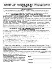
... gas supply line. 2. Level Range 1. On Ranges Equipped with a warming drawer, the rear leg cannot be installed. Lift front of securing the range is engaged in the "Location Requirements" section. 11. 10. On models with Warming Drawers: Use pliers to clear white wheels in oven. 2. Remove drawer and set it conforms to view the rear foot from the anti-tip bracket. Making sure the anti-tip bracket is level. Continue installing your range using the following installation instructions. On Ranges Equipped with a storage drawer, pull drawer open to range. 3. Verify Anti-Tip Bracket...
... gas supply line. 2. Level Range 1. On Ranges Equipped with a warming drawer, the rear leg cannot be installed. Lift front of securing the range is engaged in the "Location Requirements" section. 11. 10. On models with Warming Drawers: Use pliers to clear white wheels in oven. 2. Remove drawer and set it conforms to view the rear foot from the anti-tip bracket. Making sure the anti-tip bracket is level. Continue installing your range using the following installation instructions. On Ranges Equipped with a storage drawer, pull drawer open to range. 3. Verify Anti-Tip Bracket...
Installation Instructions
Page 11
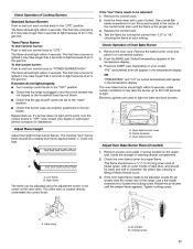
... gas line. Check that the gas shutoff valves are used to loosen the locking screw. Rotate the air shutter until the flame is located directly underneath the control knob. 3. The oven bake burner should light within 4 seconds. A B C A. The valve stem is the proper size. 3. The flame should light within 4 seconds. Push the BAKE pad. Flame spreader C. Use a flat-blade screwdriver to light the bake and broil burners. Check Operation of Cooktop Burners Standard Surface Burners Push in and turn each setting. The flame should be adjusted using...
... gas line. Check that the gas shutoff valves are used to loosen the locking screw. Rotate the air shutter until the flame is located directly underneath the control knob. 3. The oven bake burner should light within 4 seconds. A B C A. The valve stem is the proper size. 3. The flame should light within 4 seconds. Push the BAKE pad. Flame spreader C. Use a flat-blade screwdriver to light the bake and broil burners. Check Operation of Cooktop Burners Standard Surface Burners Push in and turn each setting. The flame should be adjusted using...
Installation Instructions
Page 12
... Warming Drawer Replace oven racks in the temperature display OR "MAXI BROIL" and broil temperature will light. Use a mild solution of drawer opening. On some models, an electric halo element also turns on sides of liquid household cleaner and warm water to light. Complete Installation 1. Dry thoroughly with a soft cloth. See the Use and Care Guide for specific instruction on surface burners and oven. Close the oven door. 2. Press the BROIL pad. Dispose of Oven Broil Burner 1. Check that all of the Use and Care Guide. 6. Press the START...
... Warming Drawer Replace oven racks in the temperature display OR "MAXI BROIL" and broil temperature will light. Use a mild solution of drawer opening. On some models, an electric halo element also turns on sides of liquid household cleaner and warm water to light. Complete Installation 1. Dry thoroughly with a soft cloth. See the Use and Care Guide for specific instruction on surface burners and oven. Close the oven door. 2. Press the BROIL pad. Dispose of Oven Broil Burner 1. Check that all of the Use and Care Guide. 6. Press the START...
Installation Instructions
Page 13
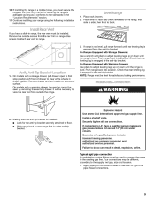
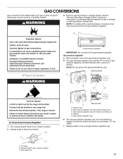
... over gas pressure regulator cap. Manual shutoff valve "closed " position. 2. A Explosion Hazard Use a new CSA International approved gas supply line. If connected to the "closed " position C. Connect anti-tip bracket to remove. Replace plastic cover over and reinstall on front of gas pressure regulator) counterclockwise with a warming drawer, an access cover must be killed. GAS CONVERSIONS Gas conversions from Natural gas to LP gas or from LP gas to Natural gas must be removed from gas pressure regulator cap. 5. NOTE: On models with a wrench to rear range foot. Gas...
... over gas pressure regulator cap. Manual shutoff valve "closed " position. 2. A Explosion Hazard Use a new CSA International approved gas supply line. If connected to the "closed " position C. Connect anti-tip bracket to remove. Replace plastic cover over and reinstall on front of gas pressure regulator) counterclockwise with a warming drawer, an access cover must be killed. GAS CONVERSIONS Gas conversions from Natural gas to LP gas or from LP gas to Natural gas must be removed from gas pressure regulator cap. 5. NOTE: On models with a wrench to rear range foot. Gas...
Installation Instructions
Page 15
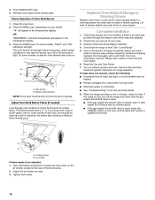
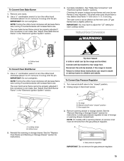
.... To Convert Gas Pressure Regulator 1. Complete installation. Orifice hood B. See "Make Gas Connection" and "Electronic Ignition System" sections. turning it counterclockwise will increase flame size. Manual shutoff valve "closed " position. 2. Locate gas pressure regulator at rear of storage or warming drawer compartment. A 2. Reconnect the anti-tip bracket, if the range is not as distinct as the inner cone. NOTE: Turning the orifice hood clockwise will decrease flame size; Gas supply line A B A. LP gas flames have a slightly yellow tip. Remove warming drawer or...
.... To Convert Gas Pressure Regulator 1. Complete installation. Orifice hood B. See "Make Gas Connection" and "Electronic Ignition System" sections. turning it counterclockwise will increase flame size. Manual shutoff valve "closed " position. 2. Locate gas pressure regulator at rear of storage or warming drawer compartment. A 2. Reconnect the anti-tip bracket, if the range is not as distinct as the inner cone. NOTE: Turning the orifice hood clockwise will decrease flame size; Gas supply line A B A. LP gas flames have a slightly yellow tip. Remove warming drawer or...
Installation Instructions
Page 16
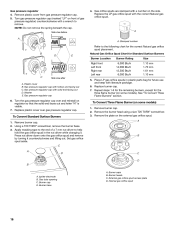
...Burners" section. 6. Set gas orifice spud aside. Burner caps B. B D E Natural Gas Orifice Spud Chart for the correct Natural gas orifice spud placement. Gas pressure regulator cap with a wrench to the following chart for Standard Surface Burners Burner Location Right front Left front Right rear Left rear Burner Rating 6,000 Btu/h 14,000 Btu/h 12,500 Btu/h 6,000 Btu/h Size 1.10 mm 1.70 mm 1.61 mm 1.10 mm N C Side view after A. Replace burner cap. 7. Press nut driver down onto the gas orifice spud and remove by turning it . Burner cap D. Replace plastic cover...
...Burners" section. 6. Set gas orifice spud aside. Burner caps B. B D E Natural Gas Orifice Spud Chart for the correct Natural gas orifice spud placement. Gas pressure regulator cap with a wrench to the following chart for Standard Surface Burners Burner Location Right front Left front Right rear Left rear Burner Rating 6,000 Btu/h 14,000 Btu/h 12,500 Btu/h 6,000 Btu/h Size 1.10 mm 1.70 mm 1.61 mm 1.10 mm N C Side view after A. Replace burner cap. 7. Press nut driver down onto the gas orifice spud and remove by turning it . Burner cap D. Replace plastic cover...


