
Use & Care Guide
Page 3
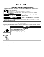
...bracket fastened down properly. All safety messages will not tip during normal use. See the installation instructions for the anti-tip bracket securely attached to potential hazards that can be killed. WARNING: This product contains one or more chemicals known to the State of California to ...reduce the chance of injury, and tell you to floor. • Slide range back so rear range foot is installed: • Slide range forward. • Look for details. This symbol alerts you what the potential hazard is, tell you how to cause...
...bracket fastened down properly. All safety messages will not tip during normal use. See the installation instructions for the anti-tip bracket securely attached to potential hazards that can be killed. WARNING: This product contains one or more chemicals known to the State of California to ...reduce the chance of injury, and tell you to floor. • Slide range back so rear range foot is installed: • Slide range forward. • Look for details. This symbol alerts you what the potential hazard is, tell you how to cause...
Use & Care Guide
Page 4
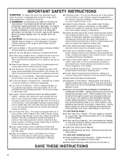
...Clean Cooktop With Caution - SAVE THESE INSTRUCTIONS 4 TO CHECK IF THE DEVICES ARE INSTALLED PROPERLY, SLIDE RANGE FORWARD, LOOK FOR ANTI-TIP BRACKET SECURELY ATTACHED TO FLOOR, AND SLIDE RANGE BACK SO REAR RANGE FOOT IS UNDER ANTI-TIP BRACKET. ■ CAUTION: Do not store items of interest to direct...9632; Keep Oven Vent Ducts Unobstructed. ■ Placement of the appliance may penetrate the broken cooktop and create a risk of fire, electrical shock, injury to cool. Build-up of pressure may cause container to cause burns. All other flammable materials contact surface units or ...
...Clean Cooktop With Caution - SAVE THESE INSTRUCTIONS 4 TO CHECK IF THE DEVICES ARE INSTALLED PROPERLY, SLIDE RANGE FORWARD, LOOK FOR ANTI-TIP BRACKET SECURELY ATTACHED TO FLOOR, AND SLIDE RANGE BACK SO REAR RANGE FOOT IS UNDER ANTI-TIP BRACKET. ■ CAUTION: Do not store items of interest to direct...9632; Keep Oven Vent Ducts Unobstructed. ■ Placement of the appliance may penetrate the broken cooktop and create a risk of fire, electrical shock, injury to cool. Build-up of pressure may cause container to cause burns. All other flammable materials contact surface units or ...
Use & Care Guide
Page 31
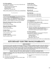
...unit elements 31 Our consultants provide assistance with: ■ Features and specifications on "applianceaccessories.com." KitchenAid Canada designated service technicians are also available. KITCHENAID® ELECTRIC RANGE WARRANTY LIMITED WARRANTY For one year from the date of purchase, when this major appliance is ... or Canada and applies only when the major appliance is operated and maintained according to instructions attached to or furnished with the product, KitchenAid brand of purchase, when this appliance is required to obtain service under this limited warranty does...
...unit elements 31 Our consultants provide assistance with: ■ Features and specifications on "applianceaccessories.com." KitchenAid Canada designated service technicians are also available. KITCHENAID® ELECTRIC RANGE WARRANTY LIMITED WARRANTY For one year from the date of purchase, when this major appliance is ... or Canada and applies only when the major appliance is operated and maintained according to instructions attached to or furnished with the product, KitchenAid brand of purchase, when this appliance is required to obtain service under this limited warranty does...
Installation Guide
Page 10
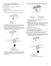
...black horizontal cross brace and through the strain relief, allowing enough slack to easily attach the wiring to : 4-wire receptacle (NEMA type 14-50R) A UL listed, 250-volt minimum, 40-amp, range power supply cord 4-wire connection: Power supply cord Style 2: Direct wire strain relief... ■ Remove the knockout as needed for your type of electrical connection: 4-wire (recommended) 3-wire (if 4-wire is not available) Electrical Connection Options If your home has:...
...black horizontal cross brace and through the strain relief, allowing enough slack to easily attach the wiring to : 4-wire receptacle (NEMA type 14-50R) A UL listed, 250-volt minimum, 40-amp, range power supply cord 4-wire connection: Power supply cord Style 2: Direct wire strain relief... ■ Remove the knockout as needed for your type of electrical connection: 4-wire (recommended) 3-wire (if 4-wire is not available) Electrical Connection Options If your home has:...
Installation Guide
Page 11
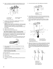
...In an area where local codes prohibit grounding through the strain relief on the cord/conduit plate on bottom of the range. Ground-link screw C. Allow enough slack to easily attach the wiring to the terminal block. Green ground wire E. Power supply cord wires 4. Ground-link screw C. A ... F E A B C A. Connect line 2 (red) and line 1 (black) wires to the range with one of the 10-32 hex nuts. Feed the power supply cord through the neutral. 1. The ground wire must be attached first. Terminal block B. Neutral (center) wire F. Ground-link screw C. Line 1 (black) 6. A ...
...In an area where local codes prohibit grounding through the strain relief on the cord/conduit plate on bottom of the range. Ground-link screw C. Allow enough slack to easily attach the wiring to the terminal block. Green ground wire E. Power supply cord wires 4. Ground-link screw C. A ... F E A B C A. Connect line 2 (red) and line 1 (black) wires to the range with one of the 10-32 hex nuts. Feed the power supply cord through the neutral. 1. The ground wire must be attached first. Terminal block B. Neutral (center) wire F. Ground-link screw C. Line 1 (black) 6. A ...
Installation Guide
Page 12
... wires. Tighten strain relief screws. 6. Strip outer covering back 3" (7.6 cm) to the outer terminal block posts with ranges. 5. Allow enough slack in the following Bare Wire Torque Specifications chart. Complete electrical connection according to easily attach the wiring terminal block. 3. Ground-link screw C. Bare (green) ground wire E. Line 2 (red) wire D. Depending on bottom...
... wires. Tighten strain relief screws. 6. Strip outer covering back 3" (7.6 cm) to the outer terminal block posts with ranges. 5. Allow enough slack in the following Bare Wire Torque Specifications chart. Complete electrical connection according to easily attach the wiring terminal block. 3. Ground-link screw C. Bare (green) ground wire E. Line 2 (red) wire D. Depending on bottom...
Installation Guide
Page 13
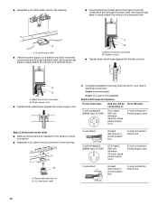
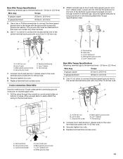
...(green) ground, and line 1 (black) wires. Setscrew C. Line 1 (black) C. C 5. Securely tighten hex nuts. 9. Allow enough slack to easily attach the wiring to the terminal block - 20 lbs-in. (2.3 N-m) Wire Awg Torque 8 gauge copper 6 gauge aluminum 25 lbs-in. (2.8 N-m) 35 lbs-in...of range. D FE A. Line 1 (black) G. Terminal lug 4. Line 2 (red) wire E. Ground-link screw DE E. Neutral (white) wire F. Line 2 (red) C. A B A G C D E B F C A. 10-32 hex nut B. Line 2 (red) wire D. Replace terminal block access cover. The ground wire must be attached first ...
...(green) ground, and line 1 (black) wires. Setscrew C. Line 1 (black) C. C 5. Securely tighten hex nuts. 9. Allow enough slack to easily attach the wiring to the terminal block - 20 lbs-in. (2.3 N-m) Wire Awg Torque 8 gauge copper 6 gauge aluminum 25 lbs-in. (2.8 N-m) 35 lbs-in...of range. D FE A. Line 1 (black) G. Terminal lug 4. Line 2 (red) wire E. Ground-link screw DE E. Neutral (white) wire F. Line 2 (red) C. A B A G C D E B F C A. 10-32 hex nut B. Line 2 (red) wire D. Replace terminal block access cover. The ground wire must be attached first ...
Installation Guide
Page 14
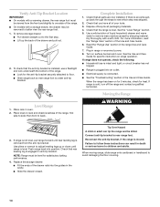
... installed, use a flashlight and look underneath the bottom of the range. ■ Look for the anti-tip bracket securely attached to side; Check that you have all parts are now installed. Turn on range operation. See the Use and Care Guide for specific instruction on ...the drawer may be killed. If range is not level, pull range forward until range is engaged in the cavity. ■ Slide the drawer closed. Dry thoroughly with a soft cloth. or circuit breaker has not tripped. ■ Range is plugged into an outlet. ■ Electrical supply is removed from the front...
... installed, use a flashlight and look underneath the bottom of the range. ■ Look for the anti-tip bracket securely attached to side; Check that you have all parts are now installed. Turn on range operation. See the Use and Care Guide for specific instruction on ...the drawer may be killed. If range is not level, pull range forward until range is engaged in the cavity. ■ Slide the drawer closed. Dry thoroughly with a soft cloth. or circuit breaker has not tripped. ■ Range is plugged into an outlet. ■ Electrical supply is removed from the front...
Installation Guide
Page 15
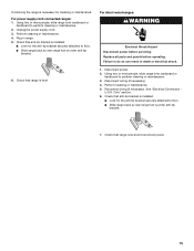
... cleaning or maintenance. 5. If removing the range is necessary for the anti-tip bracket securely attached to floor. ■ Slide range back so rear range foot is under anti-tip bracket. 6. Using two or more people, slide range onto cardboard or hardboard to perform cleaning or maintenance. 2. Plug in death or electrical shock. 1. Only" section. 6. Check that anti...
... cleaning or maintenance. 5. If removing the range is necessary for the anti-tip bracket securely attached to floor. ■ Slide range back so rear range foot is under anti-tip bracket. 6. Using two or more people, slide range onto cardboard or hardboard to perform cleaning or maintenance. 2. Plug in death or electrical shock. 1. Only" section. 6. Check that anti...