
Instruction Manual
Page 1
... or service on the warranty card, and in the space provided below. Refer to read through this instruction manual. Model KTC-V500N Serial number PRINTED IN JAPAN B64-2141-00 (K) (DT) For your records Record the serial number, found on the back of the unit, in the spaces designated on the product. KENWOOD KTC-V500N TV TUNER ► page 2 - 5 INSTRUCTION MANUAL SYNTONISEUR TV ► page 6 - 9 MODE D'EMPLOI SINTONIZADOR TV...
... or service on the warranty card, and in the space provided below. Refer to read through this instruction manual. Model KTC-V500N Serial number PRINTED IN JAPAN B64-2141-00 (K) (DT) For your records Record the serial number, found on the back of the unit, in the spaces designated on the product. KENWOOD KTC-V500N TV TUNER ► page 2 - 5 INSTRUCTION MANUAL SYNTONISEUR TV ► page 6 - 9 MODE D'EMPLOI SINTONIZADOR TV...
Instruction Manual
Page 2
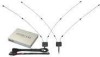
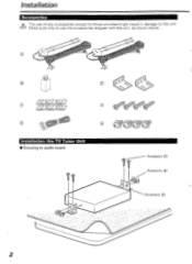
Make sure only to use of any accessories except for those provided might result in damage to audio board IT 4y (Accessory C)) (Accessory ID) (Accessory Or 2 Installation Accessories The use the accessories shipped with the unit, as shown above. 'I • le„, 41 - • 0 O O 0 O c 41 Installation the TV Tuner Unit MI Securing to the unit.
Make sure only to use of any accessories except for those provided might result in damage to audio board IT 4y (Accessory C)) (Accessory ID) (Accessory Or 2 Installation Accessories The use the accessories shipped with the unit, as shown above. 'I • le„, 41 - • 0 O O 0 O c 41 Installation the TV Tuner Unit MI Securing to the unit.
Instruction Manual
Page 3
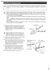
... (91 1. Rear window /". Installing the Antenna Units A Incar antennas have a lower reception sensitivity than antennas intended for 24 hours. iL • Attach the antenna to sit undisturbed for outside ' mounting. Rear seat 3 Antenna parts Antenna unit A•• Clean the glass thoroughly as on the power of the double-sided tape, but may also cause it to come loose. 2 Remove the protective strips from the installation location using the...
... (91 1. Rear window /". Installing the Antenna Units A Incar antennas have a lower reception sensitivity than antennas intended for 24 hours. iL • Attach the antenna to sit undisturbed for outside ' mounting. Rear seat 3 Antenna parts Antenna unit A•• Clean the glass thoroughly as on the power of the double-sided tape, but may also cause it to come loose. 2 Remove the protective strips from the installation location using the...
Instruction Manual
Page 4
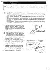
... the field of view during this time. 5 Wire the antenna cable to dry. A cold window glass surface will weaken the adhesive strength of the doublesided tape. • Do not install the antenna in a location where it by firmly pressing down from the antenna parts and the back of the antenna unit. 3 Attach the double-sided tape of the rear window using the supplied dampers...
... the field of view during this time. 5 Wire the antenna cable to dry. A cold window glass surface will weaken the adhesive strength of the doublesided tape. • Do not install the antenna in a location where it by firmly pressing down from the antenna parts and the back of the antenna unit. 3 Attach the double-sided tape of the rear window using the supplied dampers...
Instruction Manual
Page 5
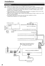
... the ignition key. Please avoid installation on Q.t..? Ignition key switch ex= o Battery ACC Ignition wire (Red) C)12V e Ground wire (Black) (To car chassis) (Accessory O0 Remove the protective sheet on uneven surfaces. the black connector before the KTC-V500N is installed, check whether the brake lamps, blinkers, wipers, etc. Installation Connection A • Make sure to ground the unit to a negative 12V DC power supply. ' • If your...
... the ignition key. Please avoid installation on Q.t..? Ignition key switch ex= o Battery ACC Ignition wire (Red) C)12V e Ground wire (Black) (To car chassis) (Accessory O0 Remove the protective sheet on uneven surfaces. the black connector before the KTC-V500N is installed, check whether the brake lamps, blinkers, wipers, etc. Installation Connection A • Make sure to ground the unit to a negative 12V DC power supply. ' • If your...
Instruction Manual
Page 6
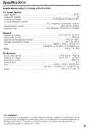
... lose the authority to operate this equipment may generate or use radio frequency energy. TV Tuner Section Color system Television system Channel converge Channel selection system Demodulation system Antenna input NTSC M 2-13 ch(VHF)/14-69 ch(UHF) PLL frequency synthesizer system Split carrier system 4-ch diversity (75 Q /3.5 r minijack) General Operating voltage Consumed current Operational temperature range Storage temperature range Size Mass 14.4 V DC (11...
... lose the authority to operate this equipment may generate or use radio frequency energy. TV Tuner Section Color system Television system Channel converge Channel selection system Demodulation system Antenna input NTSC M 2-13 ch(VHF)/14-69 ch(UHF) PLL frequency synthesizer system Split carrier system 4-ch diversity (75 Q /3.5 r minijack) General Operating voltage Consumed current Operational temperature range Storage temperature range Size Mass 14.4 V DC (11...


