

Instruction Manual
Page 1
Familiarity with installation and operation procedures will help you call upon your KENWOOD dealer for information or service on the warranty card, and in the space provided below. Model KDC-X679/MP6025/MP625 Serial number © B64-2764-00/00 (KW) For your new CD-receiver. KDC-X679 KDC-MP6025 KDC-MP625 CD-RECEIVER INSTRUCTION MANUAL Take the time...
Familiarity with installation and operation procedures will help you call upon your KENWOOD dealer for information or service on the warranty card, and in the space provided below. Model KDC-X679/MP6025/MP625 Serial number © B64-2764-00/00 (KW) For your new CD-receiver. KDC-X679 KDC-MP6025 KDC-MP625 CD-RECEIVER INSTRUCTION MANUAL Take the time...

Instruction Manual
Page 2
... Switching preout Built-in Auxiliary input Setting CD Read Setting AMP Control Receive mode Setting Basic Operations of remote 30 Accessories/ 18 Installation Procedure 32 Connecting Wires to Terminals 33 Installation 34 Removing the Unit 36 Troubleshooting Guide 37 20 Specifications 40 Frequency Offset CRSC (Clean Reception System Circuit) Text Scroll Built...
... Switching preout Built-in Auxiliary input Setting CD Read Setting AMP Control Receive mode Setting Basic Operations of remote 30 Accessories/ 18 Installation Procedure 32 Connecting Wires to Terminals 33 Installation 34 Removing the Unit 36 Troubleshooting Guide 37 20 Specifications 40 Frequency Offset CRSC (Clean Reception System Circuit) Text Scroll Built...

Instruction Manual
Page 3
...may cause harmful interference unless the modifications are designed to provide reasonable protection against harmful interference in a residential installation. If this equipment does cause harmful interference to correct the interference by one or more of the following ...may result in a particular installation. However, there is not installed and used in the instruction manual. CERTIFIES THIS EQUIPMENT CONFORMS TO DHHS REGULATIONS N0.21 CFR 1040. 10, CHAPTER 1, SUBCHAPTER J. KENWOOD CORPORATION 2967-3, ISHIKAWA-CHO, HACHIOJI-SHI TOKYO, JAPAN KENWOOD CORP. Changes or modifications ...
...may cause harmful interference unless the modifications are designed to provide reasonable protection against harmful interference in a residential installation. If this equipment does cause harmful interference to correct the interference by one or more of the following ...may result in a particular installation. However, there is not installed and used in the instruction manual. CERTIFIES THIS EQUIPMENT CONFORMS TO DHHS REGULATIONS N0.21 CFR 1040. 10, CHAPTER 1, SUBCHAPTER J. KENWOOD CORPORATION 2967-3, ISHIKAWA-CHO, HACHIOJI-SHI TOKYO, JAPAN KENWOOD CORP. Changes or modifications ...

Instruction Manual
Page 4
... injury or fire, take the following precautions: • Insert the unit all the way in until it is a piece of the unit. • Do not install the unit in place. Otherwise it is fully locked in a spot exposed to direct sunlight or excessive heat or humidity. Also avoid places with too... or metal tools) inside the unit. • If the unit starts to emit smoke or strange smells, turn off the power immediately and consult your Kenwood dealer. • Make sure not to get your fingers caught between the faceplate and the unit. • Do not apply excessive force to strong shock...
... injury or fire, take the following precautions: • Insert the unit all the way in until it is a piece of the unit. • Do not install the unit in place. Otherwise it is fully locked in a spot exposed to direct sunlight or excessive heat or humidity. Also avoid places with too... or metal tools) inside the unit. • If the unit starts to emit smoke or strange smells, turn off the power immediately and consult your Kenwood dealer. • Make sure not to get your fingers caught between the faceplate and the unit. • Do not apply excessive force to strong shock...

Instruction Manual
Page 5
...play. If the unit still does not operate normally after the Reset button has been pressed, contact your Kenwood dealer. NOTE • If you experience problems during installation, consult your Kenwood dealer for assistance. • Press the reset button if the disc auto changer fails to operate correctly... may differ from the CD and damage the unit. If the unit still fails to operate properly after a while, consult your local KENWOOD dealer for connectable models of them .) Do Not Load 3-in actual operation. Called lens fogging, CDs may form on the car heater...
...play. If the unit still does not operate normally after the Reset button has been pressed, contact your Kenwood dealer. NOTE • If you experience problems during installation, consult your Kenwood dealer for assistance. • Press the reset button if the disc auto changer fails to operate correctly... may differ from the CD and damage the unit. If the unit still fails to operate properly after a while, consult your local KENWOOD dealer for connectable models of them .) Do Not Load 3-in actual operation. Called lens fogging, CDs may form on the car heater...
Instruction Manual
Page 32
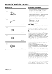
... have an ACC position, connect the ignition wires to a power source that the mounting angle is installed, check whether the brake lamps, blinkers, wipers, etc. Accessories/ Installation Procedure Accessories 1 2 3 4 5 ..........1 ..........2 ..........4 ..........4 ..........1 Installation Procedure 1. connector to both the rear output terminals (do not remove the caps on the ends of...a rear output terminal. • After the unit is 30° or less. 32 | English Always connect those wires to install the unit so that in the following order: ground, battery, ignition. 5.
... have an ACC position, connect the ignition wires to a power source that the mounting angle is installed, check whether the brake lamps, blinkers, wipers, etc. Accessories/ Installation Procedure Accessories 1 2 3 4 5 ..........1 ..........2 ..........4 ..........4 ..........1 Installation Procedure 1. connector to both the rear output terminals (do not remove the caps on the ends of...a rear output terminal. • After the unit is 30° or less. 32 | English Always connect those wires to install the unit so that in the following order: ground, battery, ignition. 5.
Instruction Manual
Page 34
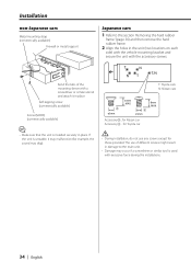
......for Nissan car Accessory4 ...for Toyota car 8mm MAX. • Make sure that the unit is used with excessive force during the installations. 34 | English Bend the tabs of the mounting sleeve with a screwdriver or similar utensil and attach it may malfunction (for those provided...the holes in place. The use any screws except for example, the sound may skip). • During installation, do not use of different screws might result in place. Installation non-Japanese cars Metal mounting strap (commercially available) Firewall or metal support Japanese cars 1 Refer to the ...
......for Nissan car Accessory4 ...for Toyota car 8mm MAX. • Make sure that the unit is used with excessive force during the installations. 34 | English Bend the tabs of the mounting sleeve with a screwdriver or similar utensil and attach it may malfunction (for those provided...the holes in place. The use any screws except for example, the sound may skip). • During installation, do not use of different screws might result in place. Installation non-Japanese cars Metal mounting strap (commercially available) Firewall or metal support Japanese cars 1 Refer to the ...

Instruction Manual
Page 40
...KDC-X679: 5000 mV/10 kΩ KDC-MP6025/MP625: 2000 mV/10 kΩ Preout impedance KDC-X679: ≤80 Ω KDC-MP6025/MP625: ≤600 kΩ Auxiliary input (KDC-MP6025) Frequency response (±1 dB) : 20 Hz - 20 kHz Input Maximum Voltage : 1200 mV Input Impedance : 100 kΩ General Operating voltage (11 - 16V allowable) : 14.4 V Current consumption : 10 A Installation...CLV 2times) Wow & Flutter : Below Measurable Limit Frequency response (±1 dB) : 10 Hz - 20 kHz Total harmonic distortion (1 kHz) KDC-X679: 0.008 % KDC-MP6025/MP625: 0.01 % Signal to change without notice.
...KDC-X679: 5000 mV/10 kΩ KDC-MP6025/MP625: 2000 mV/10 kΩ Preout impedance KDC-X679: ≤80 Ω KDC-MP6025/MP625: ≤600 kΩ Auxiliary input (KDC-MP6025) Frequency response (±1 dB) : 20 Hz - 20 kHz Input Maximum Voltage : 1200 mV Input Impedance : 100 kΩ General Operating voltage (11 - 16V allowable) : 14.4 V Current consumption : 10 A Installation...CLV 2times) Wow & Flutter : Below Measurable Limit Frequency response (±1 dB) : 10 Hz - 20 kHz Total harmonic distortion (1 kHz) KDC-X679: 0.008 % KDC-MP6025/MP625: 0.01 % Signal to change without notice.


