
Instruction Manual
Page 1
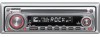
Model KDC-132/ KDC-1032/ KDC-132CR Serial number US Residence Only Register Online Register your new CD-receiver. Familiarity with installation and operation procedures will help you call upon your records Record the serial number, found on the back of the unit, in the space provided below. KDC-132 KDC-1032 KDC-132CR CD-RECEIVER INSTRUCTION MANUAL Take the time to the model and serial numbers whenever you obtain the best performance from your Kenwood product...
Model KDC-132/ KDC-1032/ KDC-132CR Serial number US Residence Only Register Online Register your new CD-receiver. Familiarity with installation and operation procedures will help you call upon your records Record the serial number, found on the back of the unit, in the space provided below. KDC-132 KDC-1032 KDC-132CR CD-RECEIVER INSTRUCTION MANUAL Take the time to the model and serial numbers whenever you obtain the best performance from your Kenwood product...
Instruction Manual
Page 2
... Notes About CDs General features Power Selecting the Source Volume Attenuator System Q Audio Control Audio Setup Speaker Setting Clock Display Adjusting Clock Theft Deterrent Faceplate Tuner features Tuning Tuning Mode Station Preset Memory Auto Memory Entry Preset Tuning CRSC (Clean Reception System Circuit) CD player features Playing CD Fast Forwarding and Reversing Track Search Track Repeat Scan Play Random Play 3 Accessories/ Installation Procedure 15 4 Connecting Wires to Terminals 16 5 Installation 17 6 Removing the Unit 19 7 Troubleshooting Guide 20 Specifications 22 11...
... Notes About CDs General features Power Selecting the Source Volume Attenuator System Q Audio Control Audio Setup Speaker Setting Clock Display Adjusting Clock Theft Deterrent Faceplate Tuner features Tuning Tuning Mode Station Preset Memory Auto Memory Entry Preset Tuning CRSC (Clean Reception System Circuit) CD player features Playing CD Fast Forwarding and Reversing Track Search Track Repeat Scan Play Random Play 3 Accessories/ Installation Procedure 15 4 Connecting Wires to Terminals 16 5 Installation 17 6 Removing the Unit 19 7 Troubleshooting Guide 20 Specifications 22 11...
Instruction Manual
Page 3
... turning the equipment off and on, the user is not installed and used in a residential installation. Location : Bottom Panel FCC WARNING This equipment may cause harmful interference to radio communications, if it is encouraged to try to operate this equipment may result in hazardous radiation exposure. English | 3 In compliance with Federal Regulations, following measures: • Reorient or relocate the receiving antenna...
... turning the equipment off and on, the user is not installed and used in a residential installation. Location : Bottom Panel FCC WARNING This equipment may cause harmful interference to radio communications, if it is encouraged to try to operate this equipment may result in hazardous radiation exposure. English | 3 In compliance with Federal Regulations, following measures: • Reorient or relocate the receiving antenna...
Instruction Manual
Page 4
...unit to malfunction. • Do not use the wrong screws, you turn on the car heater in cold weather, dew or condensation may form on the lens may cause your fingers. • Do not subject the faceplate to play. In such a situation, remove the disc and wait for the condensation to direct... When replacing a fuse, only use a new fuse with too much dust or the possibility of water splashing. (Faceplate case : KDC-1032/ 132CR only) • To prevent deterioration, do not touch the terminals of the unit or faceplate with Canadian ICES-003. If the unit still does not operate normally ...
...unit to malfunction. • Do not use the wrong screws, you turn on the car heater in cold weather, dew or condensation may form on the lens may cause your fingers. • Do not subject the faceplate to play. In such a situation, remove the disc and wait for the condensation to direct... When replacing a fuse, only use a new fuse with too much dust or the possibility of water splashing. (Faceplate case : KDC-1032/ 132CR only) • To prevent deterioration, do not touch the terminals of the unit or faceplate with Canadian ICES-003. If the unit still does not operate normally ...
Instruction Manual
Page 5
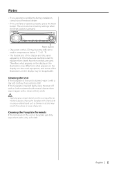
... Unit If the faceplate of this manual are used. Cleaning the Faceplate Terminals If the terminals on the display may scratch the surface or erases characters. English | 5 If the faceplate is pressed. Notes • If you experience problems during installation, consult your Kenwood dealer. • If the unit fails to explain more clearly how the controls are examples used to operate properly, press the Reset button...
... Unit If the faceplate of this manual are used. Cleaning the Faceplate Terminals If the terminals on the display may scratch the surface or erases characters. English | 5 If the faceplate is pressed. Notes • If you experience problems during installation, consult your Kenwood dealer. • If the unit fails to explain more clearly how the controls are examples used to operate properly, press the Reset button...
Instruction Manual
Page 6
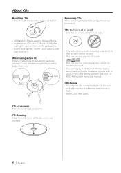
... horizontally. Use a CD-R or a CD-RW after removing the burrs with tape stuck on the CD, or use disc type accessories. This unit may not correctly play discs which do not have the mark. • You cannot play A CD-R or CD-RW that are easier to your CD-R/CD-RW writing software, and your CDR/CD-RW recorder instruction manual.) Burrs CD storage • Do not place CDs in direct sunlight (On...
... horizontally. Use a CD-R or a CD-RW after removing the burrs with tape stuck on the CD, or use disc type accessories. This unit may not correctly play discs which do not have the mark. • You cannot play A CD-R or CD-RW that are easier to your CD-R/CD-RW writing software, and your CDR/CD-RW recorder instruction manual.) Burrs CD storage • Do not place CDs in direct sunlight (On...
Instruction Manual
Page 7
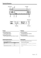
... indicator Clock display ATT indicator Power Turning ON the Power Press the [SRC] button. English | 7 When the Attenuator is ON, the "ATT" indicator blinks. Volume Increasing Volume Turn the [VOL] knob clockwise. Selecting the Source Press the [SRC] button. Each time you press the button, the Attenuator turns ON and OFF. Source required Tuner CD Standby (Illumination only mode) Display "TUnE" "CD" "STBY" Attenuator Turning the volume down quickly. Decreasing Volume Turn the [VOL] knob counterclockwise. Press the [ATT] button. Turning...
... indicator Clock display ATT indicator Power Turning ON the Power Press the [SRC] button. English | 7 When the Attenuator is ON, the "ATT" indicator blinks. Volume Increasing Volume Turn the [VOL] knob clockwise. Selecting the Source Press the [SRC] button. Each time you press the button, the Attenuator turns ON and OFF. Source required Tuner CD Standby (Illumination only mode) Display "TUnE" "CD" "STBY" Attenuator Turning the volume down quickly. Decreasing Volume Turn the [VOL] knob counterclockwise. Press the [ATT] button. Turning...
Instruction Manual
Page 8
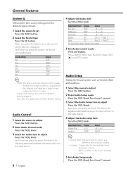
...4 Adjust the Audio setup item Turn the [VOL] knob. Audio Control 1 Select the source to adjust Press the [SRC] button. 2 Enter Audio Control mode Press the [VOL] knob. 3 Select the Audio item to set Press the [SRC] button. 2 Select the Sound type Press the [Q] button. Adjustment Item Display Range Bass level "BAS" -8 - +8 Middle level "MID" -8 - +8 Treble level "TRE" -8 - +8 Balance "BL" Left 15 - General features System Q Selecting the best sound setting preset for different types of music. 1 Select the source to adjust Press the [VOL] knob. Adjustment Item Display...
...4 Adjust the Audio setup item Turn the [VOL] knob. Audio Control 1 Select the source to adjust Press the [SRC] button. 2 Enter Audio Control mode Press the [VOL] knob. 3 Select the Audio item to set Press the [SRC] button. 2 Select the Sound type Press the [Q] button. Adjustment Item Display Range Bass level "BAS" -8 - +8 Middle level "MID" -8 - +8 Treble level "TRE" -8 - +8 Balance "BL" Left 15 - General features System Q Selecting the best sound setting preset for different types of music. 1 Select the source to adjust Press the [VOL] knob. Adjustment Item Display...

Instruction Manual
Page 9
... [SRC] button. Speaker type OFF For 5 & 4 in . Adjusting Clock 1 Enter Standby Press the [SRC] button. speaker For 6 & 6x9 in . Select the "STBY" display. 2 Select the clock display Press the [CLK] button. 3 Enter clock adjustment mode Press the [CLK] button for at least 2 seconds. Each time you press the button, the clock display turns ON and OFF. Adjust the minutes Push the Control knob towards [FM] or [AM]. English | 9 Each time you turn the knob, the setting alternates...
... [SRC] button. Speaker type OFF For 5 & 4 in . Adjusting Clock 1 Enter Standby Press the [SRC] button. speaker For 6 & 6x9 in . Select the "STBY" display. 2 Select the clock display Press the [CLK] button. 3 Enter clock adjustment mode Press the [CLK] button for at least 2 seconds. Each time you press the button, the clock display turns ON and OFF. Adjust the minutes Push the Control knob towards [FM] or [AM]. English | 9 Each time you turn the knob, the setting alternates...
Instruction Manual
Page 10
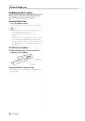
... to use the unit. 10 | English Removing the Faceplate Press the Release button. Reattaching the Faceplate 1 Align the projections on the unit with too much dust or the possibility of water splashing. Projections Grooves 2 Push the faceplate in its faceplate case while detached. (Faceplate case : Accessory of the KDC-1032/ 132CR) • Do not expose the faceplate and the faceplate case to direct sunlight...
... to use the unit. 10 | English Removing the Faceplate Press the Release button. Reattaching the Faceplate 1 Align the projections on the unit with too much dust or the possibility of water splashing. Projections Grooves 2 Push the faceplate in its faceplate case while detached. (Faceplate case : Accessory of the KDC-1032/ 132CR) • Do not expose the faceplate and the faceplate case to direct sunlight...
Instruction Manual
Page 11
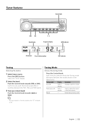
... display 1 - 6 Frequency display AUTO indicator ST indicator Preset station number CRSC indicator Tuning Selecting the station. 1 Select tuner source Press the [SRC] button. Select the "TUnE" display. 2 Select the band Push the Control knob towards [4] or [¢]. Each time you press the knob, the Tuning mode alternates between the FM1, FM2, and FM3 bands. 3 Tune up or down band Push the Control knob towards [FM] or [AM]. Tuning mode Auto seek Display "AUTO 1" indicator Operation Automatic search for a station. Tuning Mode Choose the tuning mode. Each time...
... display 1 - 6 Frequency display AUTO indicator ST indicator Preset station number CRSC indicator Tuning Selecting the station. 1 Select tuner source Press the [SRC] button. Select the "TUnE" display. 2 Select the band Push the Control knob towards [4] or [¢]. Each time you press the knob, the Tuning mode alternates between the FM1, FM2, and FM3 bands. 3 Tune up or down band Push the Control knob towards [FM] or [AM]. Tuning mode Auto seek Display "AUTO 1" indicator Operation Automatic search for a station. Tuning Mode Choose the tuning mode. Each time...

Instruction Manual
Page 12
... [1] - [6] button. 12 | English Tuner features Station Preset Memory Putting a station in the memory. 1 Select the band Push the Control knob towards [FM] or [AM]. 2 Select the frequency to the FM station. Press the [CRSC] button for at least 1 second. Each time you press the button, CRSC turns ON and OFF. On each [1] - [6] button. When CRSC is ON, the CRSC indicator is ON. The preset number display blinks 1 time. Preset Tuning Recalling the stations in the memory Auto Memory Entry...
... [1] - [6] button. 12 | English Tuner features Station Preset Memory Putting a station in the memory. 1 Select the band Push the Control knob towards [FM] or [AM]. 2 Select the frequency to the FM station. Press the [CRSC] button for at least 1 second. Each time you press the button, CRSC turns ON and OFF. On each [1] - [6] button. When CRSC is ON, the CRSC indicator is ON. The preset number display blinks 1 time. Preset Tuning Recalling the stations in the memory Auto Memory Entry...
Instruction Manual
Page 14
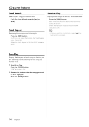
... Control knob towards [4] or [¢]. Each time you want to hear is played Press the [SCAN] button. 14 | English Press the [RDM] button. When the Random mode is ON, the "RDM" indicator is ON. CD player features Track Search Selecting the song you want to hear. 1 Start Scan Play Press the [SCAN] button. Scan Play Playing the first part of each song on the disc...
... Control knob towards [4] or [¢]. Each time you want to hear is played Press the [SCAN] button. 14 | English Press the [RDM] button. When the Random mode is ON, the "RDM" indicator is ON. CD player features Track Search Selecting the song you want to hear. 1 Start Scan Play Press the [SCAN] button. Scan Play Playing the first part of each song on the disc...
Instruction Manual
Page 15
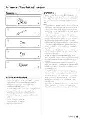
..., remove the key from the ignition and disconnect the - Connect the speaker wires of the unconnected wires or the terminals. • Connect the speaker wires correctly to the terminals to the power source running through the fuse box. • If the power is not turned ON (or it is 30° or less. connector to the unit. 6. battery. 2. Connect the wiring harness connector to a rear output terminal. • After the unit is installed, check...
..., remove the key from the ignition and disconnect the - Connect the speaker wires of the unconnected wires or the terminals. • Connect the speaker wires correctly to the terminals to the power source running through the fuse box. • If the power is not turned ON (or it is 30° or less. connector to the unit. 6. battery. 2. Connect the wiring harness connector to a rear output terminal. • After the unit is installed, check...
Instruction Manual
Page 16
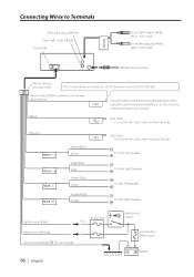
... the antenna control terminal in the vehicle. (Blue) ANT. Power control/Motor antenna control wire (Blue/White) P.CONT Connect either to the power control terminal when using the optional power amplifier, or to Terminals Rear left output (White) Rear right output (Red) Fuse (10A) FRONT Front right output (Red) (KDC-1032 only) Front left speaker To rear right speaker Ignition wire (Red) Car fuse box ACC Battery wire (Yellow) Ground wire (Black) · (To car chassis) 16 | English + Ignition key switch Car fuse box (Main fuse) - Battery...
... the antenna control terminal in the vehicle. (Blue) ANT. Power control/Motor antenna control wire (Blue/White) P.CONT Connect either to the power control terminal when using the optional power amplifier, or to Terminals Rear left output (White) Rear right output (Red) Fuse (10A) FRONT Front right output (Red) (KDC-1032 only) Front left speaker To rear right speaker Ignition wire (Red) Car fuse box ACC Battery wire (Yellow) Ground wire (Black) · (To car chassis) 16 | English + Ignition key switch Car fuse box (Main fuse) - Battery...
Instruction Manual
Page 17
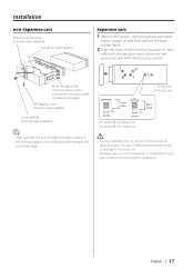
... or metal support Japanese cars 1 Refer to the main unit. • Damage may skip). • During installation, do not use any screws except for those provided. Accessory3...for Nissan car Accessory4...for example, the sound may occur if a screwdriver or similar tool is installed securely in place. If the unit is unstable, it in the unit (two locations on each side...
... or metal support Japanese cars 1 Refer to the main unit. • Damage may skip). • During installation, do not use any screws except for those provided. Accessory3...for Nissan car Accessory4...for example, the sound may occur if a screwdriver or similar tool is installed securely in place. If the unit is unstable, it in the unit (two locations on each side...

Instruction Manual
Page 19
... (page 19) and then remove the hard rubber frame. 2 Remove the screw (M4 × 8) on the back panel. 3 Insert the two removal tools deeply into the slots on the removal tool. 5 Pull the unit all the way out with ...removed from the catch pins on each side, as shown in the figure. Removing the Unit Removing the hard rubber frame 1 Engage the catch pins on the removal tool and remove the two locks on the upper level. English | 19 Upper the frame and pull it . Screw (M4X8) (commercially available) Accessory2 Removal tool 2 When the upper level is removed, remove the lower two locations...
... (page 19) and then remove the hard rubber frame. 2 Remove the screw (M4 × 8) on the back panel. 3 Insert the two removal tools deeply into the slots on the removal tool. 5 Pull the unit all the way out with ...removed from the catch pins on each side, as shown in the figure. Removing the Unit Removing the hard rubber frame 1 Engage the catch pins on the removal tool and remove the two locks on the upper level. English | 19 Upper the frame and pull it . Screw (M4X8) (commercially available) Accessory2 Removal tool 2 When the upper level is removed, remove the lower two locations...
Instruction Manual
Page 20
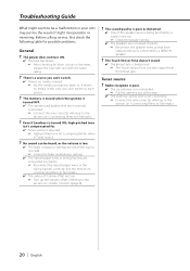
... possible problems. General ? There's a source you can't switch. ✔ There's no media in the car. ☞ Check the speaker wiring. ✔ The speakers are connected incorrectly. ☞ Reconnect the input/output wires or the wiring harness correctly. Before calling service, first check the following table for . ✔ Tuner source is connected to each output terminal is selected. ☞ High-pitched tone isn't compensated for short circuits in the wires, replace the fuse...
... possible problems. General ? There's a source you can't switch. ✔ There's no media in the car. ☞ Check the speaker wiring. ✔ The speakers are connected incorrectly. ☞ Reconnect the input/output wires or the wiring harness correctly. Before calling service, first check the following table for . ✔ Tuner source is connected to each output terminal is selected. ☞ High-pitched tone isn't compensated for short circuits in the wires, replace the fuse...
Instruction Manual
Page 21
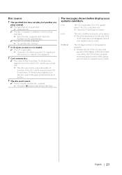
... switch off the power and consult your nearest service center. If the CD cannot be removed within 10 minutes of the section on the unit. Disc source ? The messages shown below display your nearest service center. down. If the "E-99" code does not disappear, consult your systems condition. Can't remove disc. ✔ The cause is that specified. ☞ Eject the disc magazine and check the number...
... switch off the power and consult your nearest service center. If the CD cannot be removed within 10 minutes of the section on the unit. Disc source ? The messages shown below display your nearest service center. down. If the "E-99" code does not disappear, consult your systems condition. Can't remove disc. ✔ The cause is that specified. ☞ Eject the disc magazine and check the number...
Instruction Manual
Page 22
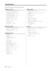
... Channel separation : 85 dB Audio section Maximum output power : 45 W x 4 Full Bandwidth Power (at less than 1% THD) : 22 W x 4 Speaker impedance : 4 - 8 Ω Tone action Bass : 100 Hz ±8 dB Middle : 1 kHz ±8 dB Treble : 10 kHz ±8 dB Preout level / Load (during disc play) : 2000 mV/10 kΩ Preout impedance : ≤ 600 Ω General Operating voltage (11 - 16V allowable) : 14.4 V Current consumption : 10 A Installation...
... Channel separation : 85 dB Audio section Maximum output power : 45 W x 4 Full Bandwidth Power (at less than 1% THD) : 22 W x 4 Speaker impedance : 4 - 8 Ω Tone action Bass : 100 Hz ±8 dB Middle : 1 kHz ±8 dB Treble : 10 kHz ±8 dB Preout level / Load (during disc play) : 2000 mV/10 kΩ Preout impedance : ≤ 600 Ω General Operating voltage (11 - 16V allowable) : 14.4 V Current consumption : 10 A Installation...


