
Instruction Manual
Page 1
... serial number, found on the back of the unit, in the space provided below. Familiarity with installation and operation procedures will help you call upon your Kenwood dealer for information or service on the warranty card, and in the spaces designated on the product. KAC-7203 STEREO/BRIDGEABLE POWER AMPLIFIER 7 page 2-7 INSTRUCTION MANUAL AMPLIFICATEUR DE PUISSANCE STEREO/COMPATIBLE 7 page 8-13 MODE D'EMPLOI ESTÉREO/AMPLIFICADOR...
... serial number, found on the back of the unit, in the space provided below. Familiarity with installation and operation procedures will help you call upon your Kenwood dealer for information or service on the warranty card, and in the spaces designated on the product. KAC-7203 STEREO/BRIDGEABLE POWER AMPLIFIER 7 page 2-7 INSTRUCTION MANUAL AMPLIFICATEUR DE PUISSANCE STEREO/COMPATIBLE 7 page 8-13 MODE D'EMPLOI ESTÉREO/AMPLIFICADOR...
Instruction Manual
Page 2
... is sent to the speaker output. • When the internal temperature is high and unit won't operate. • When a ground wire of the speakers and then connect suitable speakers to install a protective fuse in the power cord near the battery. This Product is used in the ACC ON position without turning the engine ON, it is connected to be 2Ω or greater (for stereo connections), or 4Ω or greater...
... is sent to the speaker output. • When the internal temperature is high and unit won't operate. • When a ground wire of the speakers and then connect suitable speakers to install a protective fuse in the power cord near the battery. This Product is used in the ACC ON position without turning the engine ON, it is connected to be 2Ω or greater (for stereo connections), or 4Ω or greater...
Instruction Manual
Page 3
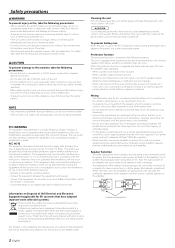
... 4 2 Speaker level input cable 1 Hexagon Wrench 1 Installation procedure Since there are large variety of the amplifier will become hot during use. terminal of the internal temperature and result in the below locations; (Unstable location, In a location that there is nothing hazardous on top of the unit. • The surface temperature of settings and connections possible according to applications, read the instruction manual well...
... 4 2 Speaker level input cable 1 Hexagon Wrench 1 Installation procedure Since there are large variety of the amplifier will become hot during use. terminal of the internal temperature and result in the below locations; (Unstable location, In a location that there is nothing hazardous on top of the unit. • The surface temperature of settings and connections possible according to applications, read the instruction manual well...
Instruction Manual
Page 4
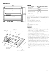
... malfunction or damage. 430 430 • Speaker level input connections Cable Color of the connector 9 White Left · White/Black 9 Gray Right · Gray/Black Genuine-accessory car stereo (No line output center unit etc.) * Commercially available parts ■ Power wire and Speaker wire connection Power control wire Power control wire Left input Right input Car fuse box ACC Battery 430 Terminal cover Battery wire* Protective Fuse* Battery Ground wire* Lead terminal* Right speaker Left speaker ■ Bridged Connections Speaker (Bridged) 4 English Do not remove caps...
... malfunction or damage. 430 430 • Speaker level input connections Cable Color of the connector 9 White Left · White/Black 9 Gray Right · Gray/Black Genuine-accessory car stereo (No line output center unit etc.) * Commercially available parts ■ Power wire and Speaker wire connection Power control wire Power control wire Left input Right input Car fuse box ACC Battery 430 Terminal cover Battery wire* Protective Fuse* Battery Ground wire* Lead terminal* Right speaker Left speaker ■ Bridged Connections Speaker (Bridged) 4 English Do not remove caps...
Instruction Manual
Page 5
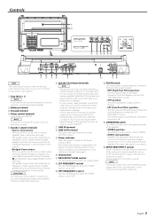
... line input terminal is output. 9 Power indicator When the power is turned on, the Power indicator lights. With this connection, shock noise may cause malfunction or damage. • Connect the power control lead to the in the instruction manual of the center unit connected with the "LPF FREQUENCY" control. NOTE For the pre-output level or the maximum power output, refer to a power supply which can be activated. English 5 BASS BOOST LEVEL control Sets the low frequency level to be used to use the unit as a high-power monaural amplifier...
... line input terminal is output. 9 Power indicator When the power is turned on, the Power indicator lights. With this connection, shock noise may cause malfunction or damage. • Connect the power control lead to the in the instruction manual of the center unit connected with the "LPF FREQUENCY" control. NOTE For the pre-output level or the maximum power output, refer to a power supply which can be activated. English 5 BASS BOOST LEVEL control Sets the low frequency level to be used to use the unit as a high-power monaural amplifier...
Instruction Manual
Page 6
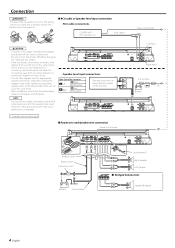
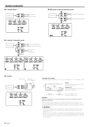
... 4 ohms. Connecting a speaker with the subwoofer. • Ensure that the withstand voltage and current ratings of the capacitors (C) and coils (L) are sufficient. System examples ■ 2-channel system CENTER UNIT L L RR Left speaker Right speaker ■ High-power 2-channel subwoofer system fž L L L CENTER UNIT RR Left subwoofer (Bridged) R L L RR gž Right subwoofer (Bridged) ■ 2-channel + Subwoofer system fž CENTER UNIT L L RR LINE OUT L L RR LINE OUT gž Left speaker (High pass) Right speaker (High pass) Subwoofer (L + R) (Bridged...
... 4 ohms. Connecting a speaker with the subwoofer. • Ensure that the withstand voltage and current ratings of the capacitors (C) and coils (L) are sufficient. System examples ■ 2-channel system CENTER UNIT L L RR Left speaker Right speaker ■ High-power 2-channel subwoofer system fž L L L CENTER UNIT RR Left subwoofer (Bridged) R L L RR gž Right subwoofer (Bridged) ■ 2-channel + Subwoofer system fž CENTER UNIT L L RR LINE OUT L L RR LINE OUT gž Left speaker (High pass) Right speaker (High pass) Subwoofer (L + R) (Bridged...
Instruction Manual
Page 7
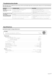
... for possible problems. PROBLEM No sound. (No sound from one side.) (Blown fuse.) The output level is too small (or too large). The sound quality is bad. (The sound is distorted.) POSSIBLE CAUSE • Input (or output) cables are disconnected. • Protection circuit may be the result of the short, replace the fuse. • Adjust the control correctly referring to . • Connect them properly checking the + / - CEA-2006 RMS Watts per channel @ 4 ohms, 1 % THD...
... for possible problems. PROBLEM No sound. (No sound from one side.) (Blown fuse.) The output level is too small (or too large). The sound quality is bad. (The sound is distorted.) POSSIBLE CAUSE • Input (or output) cables are disconnected. • Protection circuit may be the result of the short, replace the fuse. • Adjust the control correctly referring to . • Connect them properly checking the + / - CEA-2006 RMS Watts per channel @ 4 ohms, 1 % THD...


