Instruction Manual
Page 1
KAC-X811D KAC-PS811D SUBWOOFER POWER AMPLIFIER 7 page 2-9 INSTRUCTION MANUAL © B64-2794-00/00 (MV)
KAC-X811D KAC-PS811D SUBWOOFER POWER AMPLIFIER 7 page 2-9 INSTRUCTION MANUAL © B64-2794-00/00 (MV)
Instruction Manual
Page 2
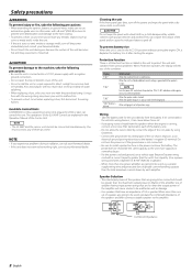
... of the unit. • Do not install the unit in Watts) of the amplifier. They can control this unit directly from the speakers when the engine is running, connect a line noise filter (optional) to each of the battery wire. • Do not allow the wire to directly contact the edge of the iron plate by each amplifier. NOTE Turn the power OFF and release the protection. Use of speakers having input power ratings that have...
... of the unit. • Do not install the unit in Watts) of the amplifier. They can control this unit directly from the speakers when the engine is running, connect a line noise filter (optional) to each of the battery wire. • Do not allow the wire to directly contact the edge of the iron plate by each amplifier. NOTE Turn the power OFF and release the protection. Use of speakers having input power ratings that have...
Instruction Manual
Page 3
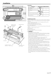
...) Hexagon socket head cap screw (M4 × 8 mm) External View Number of Items 4 4 Cover 1 Terminal cover (Power terminal) 1 Hexagon Wrench 1 Installation procedure Since there are large variety of settings and connections possible according to applications, read the instruction manual well to a place in which allows heat to the intended usage. 3.Connect the input and output wires of the units. 4.Connect the speaker wires. 5.Connect the power wire, power control wire and grounding wire following this unit in a location...
...) Hexagon socket head cap screw (M4 × 8 mm) External View Number of Items 4 4 Cover 1 Terminal cover (Power terminal) 1 Hexagon Wrench 1 Installation procedure Since there are large variety of settings and connections possible according to applications, read the instruction manual well to a place in which allows heat to the intended usage. 3.Connect the input and output wires of the units. 4.Connect the speaker wires. 5.Connect the power wire, power control wire and grounding wire following this unit in a location...
Instruction Manual
Page 4
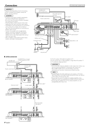
... ID numbers "1" to "7" and do not duplicate them at a time. You must connect any switch. • If the fuse blows, check wires for shorts, then replace the fuse with one of the same rating. • Check that the brake lamps, winkers, and wipers work properly. * Commercially available parts CENTER UNIT (CD receiver, etc.) Power control wire RCA cable ground terminal ��� RCA cable* Left input ��� Terminal cover Battery wire* Protective Fuse* �...
... ID numbers "1" to "7" and do not duplicate them at a time. You must connect any switch. • If the fuse blows, check wires for shorts, then replace the fuse with one of the same rating. • Check that the brake lamps, winkers, and wipers work properly. * Commercially available parts CENTER UNIT (CD receiver, etc.) Power control wire RCA cable ground terminal ��� RCA cable* Left input ��� Terminal cover Battery wire* Protective Fuse* �...
Instruction Manual
Page 5
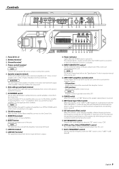
... filter) switch When this switch is set to Slave amplifiers. 0 RESET button Resets the microprocessor of the Center Unit and turn it to the Center Unit. 9 REMOTE terminals Used to connect to "-6dB"/"-12dB", frequencies in the instruction manual of the speakers should be used for amplifier control from the line input terminal is output. # Power indicator Lights when the POWER switch is set to be no less than the maximum output of 1 ohm, connect � speakers with 1-ohm or higher impedance to control the sound with this unit...
... filter) switch When this switch is set to Slave amplifiers. 0 RESET button Resets the microprocessor of the Center Unit and turn it to the Center Unit. 9 REMOTE terminals Used to connect to "-6dB"/"-12dB", frequencies in the instruction manual of the speakers should be used for amplifier control from the line input terminal is output. # Power indicator Lights when the POWER switch is set to be no less than the maximum output of 1 ohm, connect � speakers with 1-ohm or higher impedance to control the sound with this unit...
Instruction Manual
Page 6
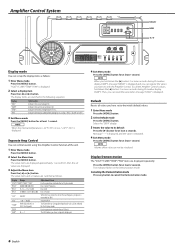
... least 1 second. The setup items and set values are switched in the following sequence. B+15 (dB) "BA Q" Q1.00/Q1.25/Q1.50/Q2.00 " EXT" ON/OFF "VOL" "TEMP" "DEFA" "AMP" -20 - 0 (dB) FAHR (Fahrenheit) or CELS (Centigrade) 0 - 7 Adjustment Item For the operation method refer to 'Display mode' Bass Center Frequency Bass level Bass Q Factor When the bass extend is displayed...
... least 1 second. The setup items and set values are switched in the following sequence. B+15 (dB) "BA Q" Q1.00/Q1.25/Q1.50/Q2.00 " EXT" ON/OFF "VOL" "TEMP" "DEFA" "AMP" -20 - 0 (dB) FAHR (Fahrenheit) or CELS (Centigrade) 0 - 7 Adjustment Item For the operation method refer to 'Display mode' Bass Center Frequency Bass level Bass Q Factor When the bass extend is displayed...
Instruction Manual
Page 7
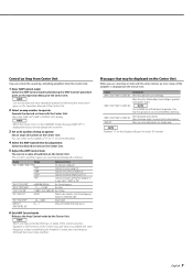
... the instructions given on the Operation Manual of the amplifier is in the Standby mode. "AMP × E-02"/"AMP × COND E-02" NOTE Turn the POWER switch Off and release the protection. NOTE When the Center Unit is displayed on the Center Unit. Indicates the source voltage (V). You can select an ID number of "0" to "7" of connected amps. 4 Select the AMP Control item for adjustment Select the desired set item...
... the instructions given on the Operation Manual of the amplifier is in the Standby mode. "AMP × E-02"/"AMP × COND E-02" NOTE Turn the POWER switch Off and release the protection. NOTE When the Center Unit is displayed on the Center Unit. Indicates the source voltage (V). You can select an ID number of "0" to "7" of connected amps. 4 Select the AMP Control item for adjustment Select the desired set item...
Instruction Manual
Page 8
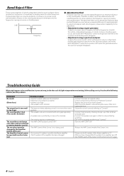
... the AMP Control mode of the Center Unit. • Always set the ID number of the Master amplifier to the frequencies causing resonance and standing waves. The output level is not pinched by anything. • Set switches properly by a screw in your ears, but we recommend the use lower volume. • After check the speaker cord and fixing the cause of the short, replace the fuse. • Adjust the control correctly...
... the AMP Control mode of the Center Unit. • Always set the ID number of the Master amplifier to the frequencies causing resonance and standing waves. The output level is not pinched by anything. • Set switches properly by a screw in your ears, but we recommend the use lower volume. • After check the speaker cord and fixing the cause of the short, replace the fuse. • Adjust the control correctly...
Instruction Manual
Page 9
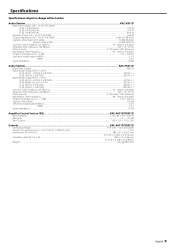
Specifications Specifications subject to Noise Ratio...100 dB Sensitivity (rated output) (MAX.) ...0.2 V Sensitivity (rated output) (MIN.) ...5.0 V Input Impedance ...10 kΩ Amplifier Control Section (EQ KAC-X811D/PS811D Bass frequency ...60 / 80 / 100 / 200 Hz Bass level ...-15 - +15 dB Bass Q factor...1.00 / 1.25 / 1.50 / 2.00 General ...KAC-X811D/PS811D Operating Voltage ...14.4 V (11 - 16 V allowable) Current Consumption (+B = 12.0 V, 100 Hz, 10 % THD, 4 Ω)...55 A Dimensions (W × H × D) ...386 × 61 ×...
Specifications Specifications subject to Noise Ratio...100 dB Sensitivity (rated output) (MAX.) ...0.2 V Sensitivity (rated output) (MIN.) ...5.0 V Input Impedance ...10 kΩ Amplifier Control Section (EQ KAC-X811D/PS811D Bass frequency ...60 / 80 / 100 / 200 Hz Bass level ...-15 - +15 dB Bass Q factor...1.00 / 1.25 / 1.50 / 2.00 General ...KAC-X811D/PS811D Operating Voltage ...14.4 V (11 - 16 V allowable) Current Consumption (+B = 12.0 V, 100 Hz, 10 % THD, 4 Ω)...55 A Dimensions (W × H × D) ...386 × 61 ×...


