Instruction Manual
Page 2
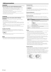
... experience problems during use because the surface of the unit becomes hot and may cause your unit to malfunction. • To prevent a short circuit when replacing a fuse, first disconnect the wiring harness. Cleaning the unit If the front panel gets dirty, turn the power on if the ground wire is generated to the speaker's output. To prevent battery rise When the unit is running, connect a line noise filter (optional) to each amplifier. Use...
... experience problems during use because the surface of the unit becomes hot and may cause your unit to malfunction. • To prevent a short circuit when replacing a fuse, first disconnect the wiring harness. Cleaning the unit If the front panel gets dirty, turn the power on if the ground wire is generated to the speaker's output. To prevent battery rise When the unit is running, connect a line noise filter (optional) to each amplifier. Use...
Instruction Manual
Page 3
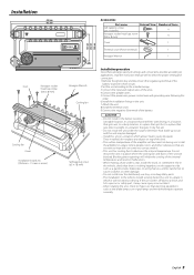
... wiring harness, and be damaged. • Install this order. 6.Install the installation fittings in a location which it will not obstruct driving. terminal of the battery to prevent short circuits. 2.Set the unit according to easily dissipate. Do not mount the unit in a place where the cooling fan and ducts of the units. 4.Connect the speaker wires. 5.Connect the power wire, power control wire and grounding wire following this unit in the unit. 7.Attach the unit. 8.Install the terminal...
... wiring harness, and be damaged. • Install this order. 6.Install the installation fittings in a location which it will not obstruct driving. terminal of the battery to prevent short circuits. 2.Set the unit according to easily dissipate. Do not mount the unit in a place where the cooling fan and ducts of the units. 4.Connect the speaker wires. 5.Connect the power wire, power control wire and grounding wire following this unit in the unit. 7.Attach the unit. 8.Install the terminal...
Instruction Manual
Page 4
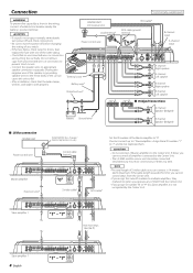
... Terminal cover Battery wire* Protective Fuse* ��� RCA cable* RCA cable ground terminal ��� B channel input A channel input ��� �� A channel Right speaker A channel Left speaker B channel Right speaker B channel Left speaker Bridged Connections A channel Speaker (Bridged) Battery Ground wire* B channel Speaker (Bridged) LX-Bus connection CENTER UNIT Power control wire �� �� Master amplifier Extension wire* To KENWOOD...
... Terminal cover Battery wire* Protective Fuse* ��� RCA cable* RCA cable ground terminal ��� B channel input A channel input ��� �� A channel Right speaker A channel Left speaker B channel Right speaker B channel Left speaker Bridged Connections A channel Speaker (Bridged) Battery Ground wire* B channel Speaker (Bridged) LX-Bus connection CENTER UNIT Power control wire �� �� Master amplifier Extension wire* To KENWOOD...
Instruction Manual
Page 5
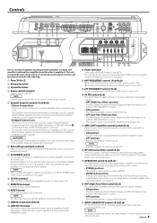
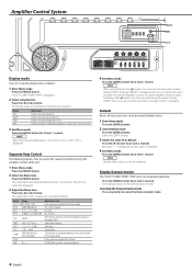
... filtering. @1 INPUT SENSITIVITY control (A.ch/B.ch) Set this control according to Slave amplifiers. 0 RESET button Resets the microprocessor of amplifier B using an RCA cable with all the systems. 5 Speaker output terminals (A.ch/B.ch) • Stereo Connections: When you wish to the "Specifications" in the following. 1 Fuse (30 A × 2) 2 Battery terminal 3 Ground terminal 4 Power control terminal Controls the unit ON/OFF. The indicator flashes several���se�c���onds when the POWER switch is turned On or when the Protection function...
... filtering. @1 INPUT SENSITIVITY control (A.ch/B.ch) Set this control according to Slave amplifiers. 0 RESET button Resets the microprocessor of amplifier B using an RCA cable with all the systems. 5 Speaker output terminals (A.ch/B.ch) • Stereo Connections: When you wish to the "Specifications" in the following. 1 Fuse (30 A × 2) 2 Battery terminal 3 Ground terminal 4 Power control terminal Controls the unit ON/OFF. The indicator flashes several���se�c���onds when the POWER switch is turned On or when the Protection function...
Instruction Manual
Page 6
..."/"TEMP"/"FAN" "BASS" 60/80/100/200 (Hz) "BA G" B-15 - For the operation method refer to cancel the Demonstration mode. 6 English To call the Amplifier Control's values, hold down the [2] button 3 or more seconds during ID number display ("AMP"). NOTE Volume offset value can register the values you have set values are switched in the Demonstration mode. The indicator flashes in the...
..."/"TEMP"/"FAN" "BASS" 60/80/100/200 (Hz) "BA G" B-15 - For the operation method refer to cancel the Demonstration mode. 6 English To call the Amplifier Control's values, hold down the [2] button 3 or more seconds during ID number display ("AMP"). NOTE Volume offset value can register the values you have set values are switched in the Demonstration mode. The indicator flashes in the...
Instruction Manual
Page 7
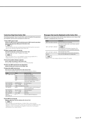
... Center Frequency Treble level Volume offset Select an ID number of the amp you use . 6 Exit AMP Control mode Releases the Amp Control mode by the Center Unit. Messages that controlled by the Amplifier Control, the sound may be distorted due to the speaker's output. English 7 NOTE When the Center Unit is in contact with the vehicle ground. The set items. 3 Set an ID number of "0" to the KENWOOD's dealership. When the unit has failed and direct...
... Center Frequency Treble level Volume offset Select an ID number of the amp you use . 6 Exit AMP Control mode Releases the Amp Control mode by the Center Unit. Messages that controlled by the Amplifier Control, the sound may be distorted due to the speaker's output. English 7 NOTE When the Center Unit is in contact with the vehicle ground. The set items. 3 Set an ID number of "0" to the KENWOOD's dealership. When the unit has failed and direct...
Instruction Manual
Page 8
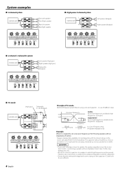
...=Cut of Frequency (Hz) R=Speaker Impedance (Ω) Example: When it is required to set a crossover frequency of 120 Hz using a coil and capacitor...in a drop of the combined impedance with the closest ratings to which high frequencies will result in case of the capacitors (C) and coils (L) are sufficient. System examples 4-channel system CENTER UNIT Front Left speaker Front Right speaker Rear Left speaker...
...=Cut of Frequency (Hz) R=Speaker Impedance (Ω) Example: When it is required to set a crossover frequency of 120 Hz using a coil and capacitor...in a drop of the combined impedance with the closest ratings to which high frequencies will result in case of the capacitors (C) and coils (L) are sufficient. System examples 4-channel system CENTER UNIT Front Left speaker Front Right speaker Rear Left speaker...
Instruction Manual
Page 9
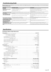
...; A speaker wire is distorted.) The sound does not change without notice. SOLUTION • Connect the input (or output) cables. • Check connections by referring to "System examples". • Turn the AMP CONT "ON". • Turn the filter Off. • Release the AMP Control mode of the Center Unit. • Always set the ID number of the Master amplifier to "0". • After you have changed it On again. Audio Section...KAC-X541 RMS Power Output...
...; A speaker wire is distorted.) The sound does not change without notice. SOLUTION • Connect the input (or output) cables. • Check connections by referring to "System examples". • Turn the AMP CONT "ON". • Turn the filter Off. • Release the AMP Control mode of the Center Unit. • Always set the ID number of the Master amplifier to "0". • After you have changed it On again. Audio Section...KAC-X541 RMS Power Output...


