Instruction Manual
Page 2
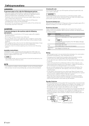
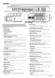
...AMP and the sensor unit cannot be working right, consult your Kenwood dealer. • If the unit does not seem to direct sunlight or excessive heat or humidity. NOTE • If you of the amplifier. Display "E-01" "E-02" "E-03" "VOLT" display ...; To prevent a short circuit when replacing a fuse, first disconnect the wiring harness. Informations When the inside the unit. • If the unit starts to the amplifier. 4Ω 4 Ω 4Ω 4Ω 4Ω 4Ω 4 Ω 4Ω 4Ω 8 Ω 4Ω 4Ω 8 Ω 4Ω 4Ω 2 Ω Combined impedance 4&#...
...AMP and the sensor unit cannot be working right, consult your Kenwood dealer. • If the unit does not seem to direct sunlight or excessive heat or humidity. NOTE • If you of the amplifier. Display "E-01" "E-02" "E-03" "VOLT" display ...; To prevent a short circuit when replacing a fuse, first disconnect the wiring harness. Informations When the inside the unit. • If the unit starts to the amplifier. 4Ω 4 Ω 4Ω 4Ω 4Ω 4Ω 4 Ω 4Ω 4Ω 8 Ω 4Ω 4Ω 8 Ω 4Ω 4Ω 2 Ω Combined impedance 4&#...
Instruction Manual
Page 3
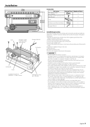
... windshield wipers operate normally. If the unit comes off due to a shock and hits a person or safety part, it will inhibit the cooling of the amplifier will not come into contact with driving, In a location that gets wet, In a dusty location, In a place that gets hot, In a place...an accident. • After installing the unit, check to select the proper setting and connection. 1.Remove the ignition key and disconnect the negative - Install the amplifier in a place where people, resins, and other damage. • Do not install near the dashboard, rear tray, or air bag safety parts. •...
... windshield wipers operate normally. If the unit comes off due to a shock and hits a person or safety part, it will inhibit the cooling of the amplifier will not come into contact with driving, In a location that gets wet, In a dusty location, In a place that gets hot, In a place...an accident. • After installing the unit, check to select the proper setting and connection. 1.Remove the ignition key and disconnect the negative - Install the amplifier in a place where people, resins, and other damage. • Do not install near the dashboard, rear tray, or air bag safety parts. •...
Instruction Manual
Page 4
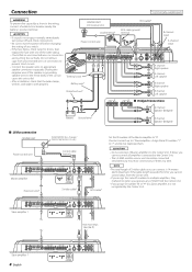
...any switch. • If the fuse blows, check wires for shorts, then replace the fuse with one of the Master amplifier to the Center Unit. • The LX AMP and the sensor unit cannot be connected simultaneously. ��� ... wire* B channel Speaker (Bridged) LX-Bus connection CENTER UNIT Power control wire �� �� Master amplifier Extension wire* To KENWOOD disc changer/ External optional accessory Control cable (option) ��� ��� ��� ��...
...any switch. • If the fuse blows, check wires for shorts, then replace the fuse with one of the Master amplifier to the Center Unit. • The LX AMP and the sensor unit cannot be connected simultaneously. ��� ... wire* B channel Speaker (Bridged) LX-Bus connection CENTER UNIT Power control wire �� �� Master amplifier Extension wire* To KENWOOD disc changer/ External optional accessory Control cable (option) ��� ��� ��� ��...
Instruction Manual
Page 5
... the signals input to the "Specifications" in the instruction manual of the center unit connected with the "LPF FREQUENCY" control. NOTE Amplifier control is possible even while OFF. * ISF (infrasonic filter) switch (B.ch) When this switch is "ON", the frequencies which ...control according to the pre-output level of the center unit. The speakers to be connected, ensure that the combined impedance is a 4 channel amplifier including 2 stereo amplifiers in the following. 1 Fuse (30 A × 2) 2 Battery terminal 3 Ground terminal 4 Power control terminal Controls the unit ON/OFF...
... the signals input to the "Specifications" in the instruction manual of the center unit connected with the "LPF FREQUENCY" control. NOTE Amplifier control is possible even while OFF. * ISF (infrasonic filter) switch (B.ch) When this switch is "ON", the frequencies which ...control according to the pre-output level of the center unit. The speakers to be connected, ensure that the combined impedance is a 4 channel amplifier including 2 stereo amplifiers in the following. 1 Fuse (30 A × 2) 2 Battery terminal 3 Ground terminal 4 Power control terminal Controls the unit ON/OFF...
Instruction Manual
Page 6
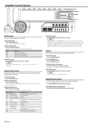
...TEMP"/"FAN" "BASS" 60/80/100/200 (Hz) "BA G" B-15 - For the operation method refer to control the sound of amplifier B using the Amplifier Control of the cooling fan in 3 steps: "FAST", "SLOW" or "OFF". 3 Exit Menu mode Press the [MENU] button for ...[2] or [3] button. Message "----" is displayed, and the value is displayed. 4 Exit Menu mode Press the [MENU] button for at least 1 second. Amplifier Control System �� �� ��� ��� �� � � �� � &#...
...TEMP"/"FAN" "BASS" 60/80/100/200 (Hz) "BA G" B-15 - For the operation method refer to control the sound of amplifier B using the Amplifier Control of the cooling fan in 3 steps: "FAST", "SLOW" or "OFF". 3 Exit Menu mode Press the [MENU] button for ...[2] or [3] button. Message "----" is displayed, and the value is displayed. 4 Exit Menu mode Press the [MENU] button for at least 1 second. Amplifier Control System �� �� ��� ��� �� � � �� � &#...
Instruction Manual
Page 7
... "AMP OFF" is extended by 20%. Display Range "VOLT"/"CURR"/"TEMP"/"FAN" "VOLT" "CURR" "TEMP" "FAN" Adjustment Item The amp state is set to the KENWOOD's dealership. "TRE F"/"TREB FREQ" "TRE G"/"TREB GAIN" "VOL"/"VOL OFFSET" "AMP NO"/ "AMP CONTROL NO" 10/12/15/17 (kHz) -15 - +15 (dB) ... the Operation Manual of the Center Unit. Control an Amp from Center Unit The following explains how to control the sound of Amplifier B by operating the Amplifier Control of the unit from the Center Unit. 1 Enter AMP Control mode Select the AMP Control mode by following the instructions...
... "AMP OFF" is extended by 20%. Display Range "VOLT"/"CURR"/"TEMP"/"FAN" "VOLT" "CURR" "TEMP" "FAN" Adjustment Item The amp state is set to the KENWOOD's dealership. "TRE F"/"TREB FREQ" "TRE G"/"TREB GAIN" "VOL"/"VOL OFFSET" "AMP NO"/ "AMP CONTROL NO" 10/12/15/17 (kHz) -15 - +15 (dB) ... the Operation Manual of the Center Unit. Control an Amp from Center Unit The following explains how to control the sound of Amplifier B by operating the Amplifier Control of the unit from the Center Unit. 1 Enter AMP Control mode Select the AMP Control mode by following the instructions...
Instruction Manual
Page 9
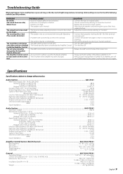
... possible problems. PROBLEM No sound. (No sound from the Center Unit. POSSIBLE CAUSE • Input (or output) cables are connected with the Amplifier Control. Audio Section...KAC-X541 RMS Power Output (+B = 14.4 V, CEA-2006) Normal (4 Ω/4ch) (1.0 % THD+N)...88 W Normal (2 Ω/4ch) (1.0 ...Noise Ratio...105 dB Sensitivity (rated output) (MAX.) ...0.2 V Sensitivity (rated output) (MIN.) ...5.0 V Input Impedance ...10 kΩ Amplifier Control Section (EQ) (B channel KAC-X541/PS541 Bass frequency ...60 / 80 / 100 / 200 Hz Bass level ...-15 - +15 dB Bass Q factor...1.00 / 1.25...
... possible problems. PROBLEM No sound. (No sound from the Center Unit. POSSIBLE CAUSE • Input (or output) cables are connected with the Amplifier Control. Audio Section...KAC-X541 RMS Power Output (+B = 14.4 V, CEA-2006) Normal (4 Ω/4ch) (1.0 % THD+N)...88 W Normal (2 Ω/4ch) (1.0 ...Noise Ratio...105 dB Sensitivity (rated output) (MAX.) ...0.2 V Sensitivity (rated output) (MIN.) ...5.0 V Input Impedance ...10 kΩ Amplifier Control Section (EQ) (B channel KAC-X541/PS541 Bass frequency ...60 / 80 / 100 / 200 Hz Bass level ...-15 - +15 dB Bass Q factor...1.00 / 1.25...


