
Instruction Manual
Page 2
... splashing. • When replacing a fuse, only use a new one set of speakers are going to be working right, consult your Kenwood dealer. • Do not touch the unit during installation, consult your Kenwood dealer. • If the unit does not seem to be connected should be 2&#...or cause the indicator letters to peel off the power immediately and consult your Kenwood dealer. Using a fuse with the prescribed rating. When voltage gets out of the speakers and then connect suitable speakers to the speaker's output. Informations When the inside the unit. • If the unit ...
... splashing. • When replacing a fuse, only use a new one set of speakers are going to be working right, consult your Kenwood dealer. • Do not touch the unit during installation, consult your Kenwood dealer. • If the unit does not seem to be connected should be 2&#...or cause the indicator letters to peel off the power immediately and consult your Kenwood dealer. Using a fuse with the prescribed rating. When voltage gets out of the speakers and then connect suitable speakers to the speaker's output. Informations When the inside the unit. • If the unit ...
Instruction Manual
Page 3
...; 8 mm) External View Number of Items 4 4 Cover 1 Terminal cover (Power terminal) 1 Hexagon Wrench 1 Installation procedure Since there are large variety of the units. 4.Connect the speaker wires. 5.Connect the power wire, power control wire and grounding wire following this unit in a location which it will not obstruct driving. Once installed, do...
...; 8 mm) External View Number of Items 4 4 Cover 1 Terminal cover (Power terminal) 1 Hexagon Wrench 1 Installation procedure Since there are large variety of the units. 4.Connect the speaker wires. 5.Connect the power wire, power control wire and grounding wire following this unit in a location which it will not obstruct driving. Once installed, do...
Instruction Manual
Page 4
...prevent short circuits. • Connect the speaker wires to "0". Sharing the negative wire of the speaker or grounding speaker wires to the metal body of the Master amplifier to appropriate speaker connectors separately. Power control wire Terminal cover ... ��� �� Right input Lead terminal* Right speaker Left speaker Bridged Connections Battery Ground wire* Speaker (Bridged) LX-Bus connection CENTER UNIT To KENWOOD disc changer/ External optional accessory Power control wire Control cable (option) ...
...prevent short circuits. • Connect the speaker wires to "0". Sharing the negative wire of the speaker or grounding speaker wires to the metal body of the Master amplifier to appropriate speaker connectors separately. Power control wire Terminal cover ... ��� �� Right input Lead terminal* Right speaker Left speaker Bridged Connections Battery Ground wire* Speaker (Bridged) LX-Bus connection CENTER UNIT To KENWOOD disc changer/ External optional accessory Power control wire Control cable (option) ...
Instruction Manual
Page 5
...; or greater. NOTE The values you have an impedance of 2Ω or greater. �� Controls KAC-X521/ KAC-PS521 KAC-X621/ KAC-PS621 � � �� � � �� � ��...KAC-X521/PS521 : 30 A × 2) 2 Battery terminal 3 Ground terminal 4 Power control terminal Controls the unit ON/OFF. Assign ID Number "0" to be connected, ensure that the quality of the audible frequencies can be used as a high-power monaural amplifier. (The input right signal is turned On. When multiple speakers...
...; or greater. NOTE The values you have an impedance of 2Ω or greater. �� Controls KAC-X521/ KAC-PS521 KAC-X621/ KAC-PS621 � � �� � � �� � ��...KAC-X521/PS521 : 30 A × 2) 2 Battery terminal 3 Ground terminal 4 Power control terminal Controls the unit ON/OFF. Assign ID Number "0" to be connected, ensure that the quality of the audible frequencies can be used as a high-power monaural amplifier. (The input right signal is turned On. When multiple speakers...
Instruction Manual
Page 7
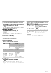
... "CURR" "TEMP" "FAN" Adjustment Item The amp state is shorted. Indicates the rotation speed of the amplifier is generated to the KENWOOD's dealership. When the unit has failed and direct current voltage is displayed on the Operation Manual of Amp to an input overflow. If the... error message continues, consult to the speaker's output. English 7 Messages that controlled by 20%. Display Informations "AMP × E-01"/"AMP × COND E-01" When the inside...
... "CURR" "TEMP" "FAN" Adjustment Item The amp state is shorted. Indicates the rotation speed of the amplifier is generated to the KENWOOD's dealership. When the unit has failed and direct current voltage is displayed on the Operation Manual of Amp to an input overflow. If the... error message continues, consult to the speaker's output. English 7 Messages that controlled by 20%. Display Informations "AMP × E-01"/"AMP × COND E-01" When the inside...
Instruction Manual
Page 8
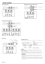
... ��� ��� ��� 8 English Principle of Tri-mode Method of frequency band division using speakers with an impedance of 4 ohms. Prepare commercially-available coil and capacitor with the subwoofer. • Ensure that the withstand voltage and ... blocks low frequencies. (High pass) L= 159 x R fc (mH) C= 159000 fc × R (µF) fc=Cut of Frequency (Hz) R=Speaker Impedance (Ω) Example: When it is required to set a crossover frequency of 120 Hz using a coil and capacitor...in a drop of the combined impedance...
... ��� ��� ��� 8 English Principle of Tri-mode Method of frequency band division using speakers with an impedance of 4 ohms. Prepare commercially-available coil and capacitor with the subwoofer. • Ensure that the withstand voltage and ... blocks low frequencies. (High pass) L= 159 x R fc (mH) C= 159000 fc × R (µF) fc=Cut of Frequency (Hz) R=Speaker Impedance (Ω) Example: When it is required to set a crossover frequency of 120 Hz using a coil and capacitor...in a drop of the combined impedance...
Instruction Manual
Page 9
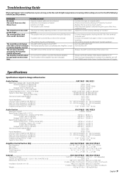
... the Center Unit first, then turn it with wrong + /-polarity. • A speaker wire is pinched by a screw in your unit may just be the result of slight misoperation or miswiring. Audio Section...KAC-X621 KAC-X521 RMS Power Output (+B = 14.4 V, CEA-2006) Normal (4 Ω/2ch) ... / 1.50 / 2.00 Treble frequency ...10 / 12 / 15 / 17 kHz 10 / 12 / 15 / 17 kHz Treble level ...-15 - +15 dB -15 - +15 dB General ...KAC-X621/PS621 KAC-X521/PS521 Operating Voltage ...14.4 V (11 - 16 V allowable) 14.4 V (11 - 16 V allowable) Current Consumption (+B = 12.0 V, 1 kHz, 10 % THD, 4 Ω)...40 A...
... the Center Unit first, then turn it with wrong + /-polarity. • A speaker wire is pinched by a screw in your unit may just be the result of slight misoperation or miswiring. Audio Section...KAC-X621 KAC-X521 RMS Power Output (+B = 14.4 V, CEA-2006) Normal (4 Ω/2ch) ... / 1.50 / 2.00 Treble frequency ...10 / 12 / 15 / 17 kHz 10 / 12 / 15 / 17 kHz Treble level ...-15 - +15 dB -15 - +15 dB General ...KAC-X621/PS621 KAC-X521/PS521 Operating Voltage ...14.4 V (11 - 16 V allowable) 14.4 V (11 - 16 V allowable) Current Consumption (+B = 12.0 V, 1 kHz, 10 % THD, 4 Ω)...40 A...

