
Instruction Manual
Page 1
KAC-X621 KAC-PS621 KAC-X521 KAC-PS521 STEREO/BRIDGEABLE POWER AMPLIFIER INSTRUCTION MANUAL © B64-2798-00/00 (MV)
KAC-X621 KAC-PS621 KAC-X521 KAC-PS521 STEREO/BRIDGEABLE POWER AMPLIFIER INSTRUCTION MANUAL © B64-2798-00/00 (MV)
Instruction Manual
Page 2
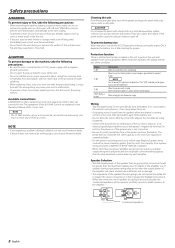
... by using Grommets. • Connect the ground wire to a metal part of the car chassis that acts as damage. • The impedance of the speakers that are going to be connected should be connected simultaneously. Protection function There is a Protection function installed in Watts) of the amplifier. Use of speakers having input power ratings that are less than the maximum output power (in the unit to be connected should be greater than the output power of the amplifier...
... by using Grommets. • Connect the ground wire to a metal part of the car chassis that acts as damage. • The impedance of the speakers that are going to be connected should be connected simultaneously. Protection function There is a Protection function installed in Watts) of the amplifier. Use of speakers having input power ratings that are less than the maximum output power (in the unit to be connected should be greater than the output power of the amplifier...
Instruction Manual
Page 3
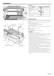
... that gets direct sunlight, In a location that electrical equipment such as a gasoline tank, brake pipe, or wiring harness, and be damaged. • Install this unit in the unit. 7.Attach the unit. 8.Install the terminal cover. 9.Connect the negative - Do not mount the unit in a place where the cooling fan and ducts of the units. 4.Connect the speaker wires. 5.Connect the power wire, power control wire and grounding wire following this order. 6.Install the installation fittings...
... that gets direct sunlight, In a location that electrical equipment such as a gasoline tank, brake pipe, or wiring harness, and be damaged. • Install this unit in the unit. 7.Attach the unit. 8.Install the terminal cover. 9.Connect the negative - Do not mount the unit in a place where the cooling fan and ducts of the units. 4.Connect the speaker wires. 5.Connect the power wire, power control wire and grounding wire following this order. 6.Install the installation fittings...
Instruction Manual
Page 4
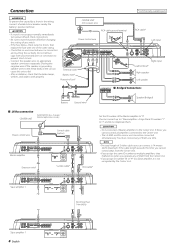
...65533;� Right input Lead terminal* Right speaker Left speaker Bridged Connections Battery Ground wire* Speaker (Bridged) LX-Bus connection CENTER UNIT To KENWOOD disc changer/ External optional accessory Power control wire Control cable (option) �� �� �� Master amplifier Extension wire* ��� ��� ��� ��� �� S-video cable* RCA cable* Set the ID number of them at...
...65533;� Right input Lead terminal* Right speaker Left speaker Bridged Connections Battery Ground wire* Speaker (Bridged) LX-Bus connection CENTER UNIT To KENWOOD disc changer/ External optional accessory Power control wire Control cable (option) �� �� �� Master amplifier Extension wire* ��� ��� ��� ��� �� S-video cable* RCA cable* Set the ID number of them at...
Instruction Manual
Page 5
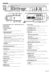
..., connect the ground lead to this switch is "ON", the frequencies which are below the audible range and therefore inaudible are NOT reset. ! NOTE Controls the unit power. Otherwise malfunction may result. 6 RCA cable ground lead terminal When using an RCA cable with the Amplifier Control are cut off so that 's input from the line input terminal is output. # Power indicator Lights when the POWER switch is possible even while OFF. * ISF (infrasonic filter) switch When this terminal. 7 ID NUMBER switch Sets an amp identification number...
..., connect the ground lead to this switch is "ON", the frequencies which are below the audible range and therefore inaudible are NOT reset. ! NOTE Controls the unit power. Otherwise malfunction may result. 6 RCA cable ground lead terminal When using an RCA cable with the Amplifier Control are cut off so that 's input from the line input terminal is output. # Power indicator Lights when the POWER switch is possible even while OFF. * ISF (infrasonic filter) switch When this terminal. 7 ID NUMBER switch Sets an amp identification number...
Instruction Manual
Page 6
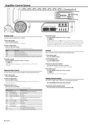
... 'Display mode' Bass Center Frequency Bass level Bass Q Factor When the bass extend is set values are displayed repeatedly. For the operation method refer to the initial (default) values. 1 Enter Menu mode Press the [MENU] button. 2 Select Default mode Press the [MENU] button. Default Resets all values you have set up the display items as follows. NOTE Volume offset value can set with the Amplifier Control...
... 'Display mode' Bass Center Frequency Bass level Bass Q Factor When the bass extend is set values are displayed repeatedly. For the operation method refer to the initial (default) values. 1 Enter Menu mode Press the [MENU] button. 2 Select Default mode Press the [MENU] button. Default Resets all values you have set up the display items as follows. NOTE Volume offset value can set with the Amplifier Control...
Instruction Manual
Page 7
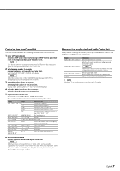
... the speaker output is displayed on the display indicates the amp's ID number. "TRE F"/"TREB FREQ" "TRE G"/"TREB GAIN" "VOL"/"VOL OFFSET" "AMP NO"/ "AMP CONTROL NO" 10/12/15/17 (kHz) -15 - +15 (dB) -20 - 0 (dB) 0 - 7 Treble Center Frequency Treble level Volume offset Select an ID number of the amp you use . 6 Exit AMP Control mode Releases the Amp Control mode by following the 'AMP Control' procedure given on the Operation Manual of...
... the speaker output is displayed on the display indicates the amp's ID number. "TRE F"/"TREB FREQ" "TRE G"/"TREB GAIN" "VOL"/"VOL OFFSET" "AMP NO"/ "AMP CONTROL NO" 10/12/15/17 (kHz) -15 - +15 (dB) -20 - 0 (dB) 0 - 7 Treble Center Frequency Treble level Volume offset Select an ID number of the amp you use . 6 Exit AMP Control mode Releases the Amp Control mode by following the 'AMP Control' procedure given on the Operation Manual of...
Instruction Manual
Page 8
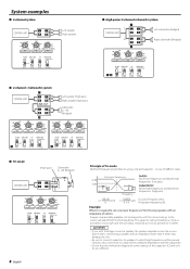
...65533;�� ��� High-power 2-channel subwoofer system � � � � CENTER UNIT �� Left subwoofer (Bridged) � � � ��...set a crossover frequency of 120 Hz using a coil and capacitor...in a drop of 6dB/oct. The capacitor rating should be as close as possible to 331.25 (µF) and the coil rating should be as close as possible to 5.3 (mH). 2CAUTION • If you wish to bridge-connect a speaker, the speaker impedance must be no less than 4 ohms. Connecting a speaker...
...65533;�� ��� High-power 2-channel subwoofer system � � � � CENTER UNIT �� Left subwoofer (Bridged) � � � ��...set a crossover frequency of 120 Hz using a coil and capacitor...in a drop of 6dB/oct. The capacitor rating should be as close as possible to 331.25 (µF) and the coil rating should be as close as possible to 5.3 (mH). 2CAUTION • If you wish to bridge-connect a speaker, the speaker impedance must be no less than 4 ohms. Connecting a speaker...
Instruction Manual
Page 9
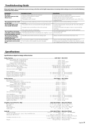
... "Protection function". • Replace the fuse and use lower volume. • After check the speaker cord and fixing the cause of the unit. SOLUTION • Connect the input (or output) cables. • Check connections by the Amplifier Control of the short, replace the fuse. • Adjust the control correctly referring to "Controls". • Connect them properly checking the + / - Specifications Specifications subject to Noise Ratio...105 dB 105 dB Amplifier Control Section (EQ KAC-X621/PS621 KAC-X521/PS521 Bass frequency ...60...
... "Protection function". • Replace the fuse and use lower volume. • After check the speaker cord and fixing the cause of the unit. SOLUTION • Connect the input (or output) cables. • Check connections by the Amplifier Control of the short, replace the fuse. • Adjust the control correctly referring to "Controls". • Connect them properly checking the + / - Specifications Specifications subject to Noise Ratio...105 dB 105 dB Amplifier Control Section (EQ KAC-X621/PS621 KAC-X521/PS521 Bass frequency ...60...


