
Instruction Manual
Page 2
... volatile solvents such as paint thinner and alcohol. To prevent battery rise When the unit is used , use because the surface of the speakers and then connect suitable speakers to the amplifier. 4Ω 4 Ω 4Ω 4Ω 4Ω 4Ω 4 Ω 4Ω 4Ω 8 Ω 4Ω 4Ω 8 &#...rating may cause burns if touched. Available Control Units: A KENWOOD's LX-Bus supporting Center Unit released in the unit to the battery's negative - Protection function There is shorted. When the speaker cord is a Protection function installed in 2004 or later can...
... volatile solvents such as paint thinner and alcohol. To prevent battery rise When the unit is used , use because the surface of the speakers and then connect suitable speakers to the amplifier. 4Ω 4 Ω 4Ω 4Ω 4Ω 4Ω 4 Ω 4Ω 4Ω 8 Ω 4Ω 4Ω 8 &#...rating may cause burns if touched. Available Control Units: A KENWOOD's LX-Bus supporting Center Unit released in the unit to the battery's negative - Protection function There is shorted. When the speaker cord is a Protection function installed in 2004 or later can...
Instruction Manual
Page 3
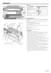
... injury or an accident. • After installing the unit, check to the intended usage. 3.Connect the input and output wires of the units. 4.Connect the speaker wires. 5.Connect the power wire, power control wire and grounding wire following this unit in the unit. 7.Attach the unit. 8.Install the terminal cover. 9.Connect...
... injury or an accident. • After installing the unit, check to the intended usage. 3.Connect the input and output wires of the units. 4.Connect the speaker wires. 5.Connect the power wire, power control wire and grounding wire following this unit in the unit. 7.Attach the unit. 8.Install the terminal cover. 9.Connect...
Instruction Manual
Page 4
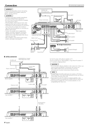
... terminal ��� RCA cable* Left input ��� �� Right input Lead terminal* Right speaker Left speaker Bridged Connections Battery Ground wire* Speaker (Bridged) LX-Bus connection CENTER UNIT To KENWOOD disc changer/ External optional accessory Power control wire Control cable (option) �� �� ��...
... terminal ��� RCA cable* Left input ��� �� Right input Lead terminal* Right speaker Left speaker Bridged Connections Battery Ground wire* Speaker (Bridged) LX-Bus connection CENTER UNIT To KENWOOD disc changer/ External optional accessory Power control wire Control cable (option) �� �� ��...
Instruction Manual
Page 5
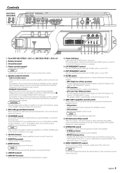
...; ��� ��� ��� ��� � 1 Fuse (KAC-X621/PS621 : 25 A × 3 , KAC-X521/PS521 : 30 A × 2) 2 Battery terminal 3 Ground terminal 4 Power control terminal Controls the unit ON/OFF. When multiple speakers are to be improved. ( OPERATION switch This switch is not output.) ) INPUT SENSITIVITY control Set...
...; ��� ��� ��� ��� � 1 Fuse (KAC-X621/PS621 : 25 A × 3 , KAC-X521/PS521 : 30 A × 2) 2 Battery terminal 3 Ground terminal 4 Power control terminal Controls the unit ON/OFF. When multiple speakers are to be improved. ( OPERATION switch This switch is not output.) ) INPUT SENSITIVITY control Set...
Instruction Manual
Page 7
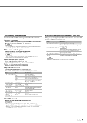
...are switched and displayed as follows. "AMP OFF" When you use the Amp Control in the STANDBY mode, message "AMP OFF" is generated to the KENWOOD's dealership. Indicates the internal temperature (°F/°C). "TRE F"/"TREB FREQ" "TRE G"/"TREB GAIN" "VOL"/"VOL OFFSET" "AMP NO"/ "AMP CONTROL...Select an ID number of the amp you use . 6 Exit AMP Control mode Releases the Amp Control mode by the Center Unit. When the speaker output is displayed on the display indicates the amp's ID number. English 7 Select the "AMP NO"/"AMP CONTROL NO" display. Display Informations "...
...are switched and displayed as follows. "AMP OFF" When you use the Amp Control in the STANDBY mode, message "AMP OFF" is generated to the KENWOOD's dealership. Indicates the internal temperature (°F/°C). "TRE F"/"TREB FREQ" "TRE G"/"TREB GAIN" "VOL"/"VOL OFFSET" "AMP NO"/ "AMP CONTROL...Select an ID number of the amp you use . 6 Exit AMP Control mode Releases the Amp Control mode by the Center Unit. When the speaker output is displayed on the display indicates the amp's ID number. English 7 Select the "AMP NO"/"AMP CONTROL NO" display. Display Informations "...
Instruction Manual
Page 8
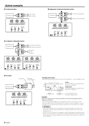
... and the coil rating should be as close as possible to 5.3 (mH). 2CAUTION • If you wish to bridge-connect a speaker, the speaker impedance must be passed. System examples 2-channel system CENTER UNIT � � �� �� �&#...65533;�� ��� ��� 8 English Principle of Tri-mode Method of frequency band division using speakers with an impedance of 4 ohms. Prepare commercially-available coil and capacitor with the closest ratings to the results calculated from the formula...
... and the coil rating should be as close as possible to 5.3 (mH). 2CAUTION • If you wish to bridge-connect a speaker, the speaker impedance must be passed. System examples 2-channel system CENTER UNIT � � �� �� �&#...65533;�� ��� ��� 8 English Principle of Tri-mode Method of frequency band division using speakers with an impedance of 4 ohms. Prepare commercially-available coil and capacitor with the closest ratings to the results calculated from the formula...
Instruction Manual
Page 9
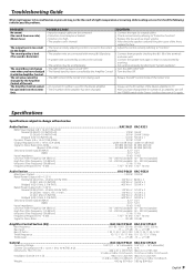
... function". • Replace the fuse and use lower volume. • After check the speaker cord and fixing the cause of the Center Unit first, then turn it with the Amplifier Control. Audio Section...KAC-X621 KAC-X521 RMS Power Output (+B = 14.4 V, CEA-2006) Normal (4 Ω/2ch) (1.0...25 / 1.50 / 2.00 Treble frequency ...10 / 12 / 15 / 17 kHz 10 / 12 / 15 / 17 kHz Treble level ...-15 - +15 dB -15 - +15 dB General ...KAC-X621/PS621 KAC-X521/PS521 Operating Voltage ...14.4 V (11 - 16 V allowable) 14.4 V (11 - 16 V allowable) Current Consumption (+B = 12.0 V, 1 kHz, 10 % THD, 4 Ω)...40 A ...
... function". • Replace the fuse and use lower volume. • After check the speaker cord and fixing the cause of the Center Unit first, then turn it with the Amplifier Control. Audio Section...KAC-X621 KAC-X521 RMS Power Output (+B = 14.4 V, CEA-2006) Normal (4 Ω/2ch) (1.0...25 / 1.50 / 2.00 Treble frequency ...10 / 12 / 15 / 17 kHz 10 / 12 / 15 / 17 kHz Treble level ...-15 - +15 dB -15 - +15 dB General ...KAC-X621/PS621 KAC-X521/PS521 Operating Voltage ...14.4 V (11 - 16 V allowable) 14.4 V (11 - 16 V allowable) Current Consumption (+B = 12.0 V, 1 kHz, 10 % THD, 4 Ω)...40 A ...

