
Instruction Manual
Page 1
... will help you call upon your KENWOOD dealer for information or service on the warranty card, and in the space provided below. For your new power amplifier. Refer to read through this instruction manual. Model KAC-X520/PS520 Serial number © PRINTED IN JAPAN B64-2277-00 / 01 (KM / EM) KAC-X520 KAC-PS520 POWER AMPLIFIER 7 page 2-13 INSTRUCTION MANUAL AMPLIFICATEUR DE PUISSANCE 7 page 14-25 MODE D'EMPLOI AMPLIFICADOR DE...
... will help you call upon your KENWOOD dealer for information or service on the warranty card, and in the space provided below. For your new power amplifier. Refer to read through this instruction manual. Model KAC-X520/PS520 Serial number © PRINTED IN JAPAN B64-2277-00 / 01 (KM / EM) KAC-X520 KAC-PS520 POWER AMPLIFIER 7 page 2-13 INSTRUCTION MANUAL AMPLIFICATEUR DE PUISSANCE 7 page 14-25 MODE D'EMPLOI AMPLIFICADOR DE...
Instruction Manual
Page 2
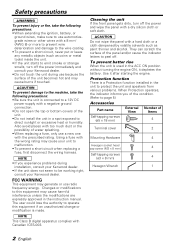
... unit to protect the unit and speakers from various problems. When Protection operates, the indicator informs you experience problems during use radio frequency energy. Use it depletes the battery. FCC WARNING This equipment may cause your Kenwood dealer. • If the unit does not seem to page 5) Accessories Part name External Number of View Items Self-tapping screws (ø5 × 18 mm) 4 Terminal cover 2 Mounting Hardware 4 Hexagon socket head cap screw...
... unit to protect the unit and speakers from various problems. When Protection operates, the indicator informs you experience problems during use radio frequency energy. Use it depletes the battery. FCC WARNING This equipment may cause your Kenwood dealer. • If the unit does not seem to page 5) Accessories Part name External Number of View Items Self-tapping screws (ø5 × 18 mm) 4 Terminal cover 2 Mounting Hardware 4 Hexagon socket head cap screw...
Instruction Manual
Page 3
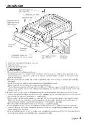
... head cap screw (M3 × 8 mm) Terminal cover Hexagon Wrench Installation board, etc. (thickness : 15 mm or more) Self-tapping screws (ø3 × 8 mm) Mounting Hardware 1. Otherwise heat build-up occurs and the unit may cause injury or an accident. • After installing the unit, check to make sure that are sensitive to heat will become hot during use. Install the installation...
... head cap screw (M3 × 8 mm) Terminal cover Hexagon Wrench Installation board, etc. (thickness : 15 mm or more) Self-tapping screws (ø3 × 8 mm) Mounting Hardware 1. Otherwise heat build-up occurs and the unit may cause injury or an accident. • After installing the unit, check to make sure that are sensitive to heat will become hot during use. Install the installation...
Instruction Manual
Page 4
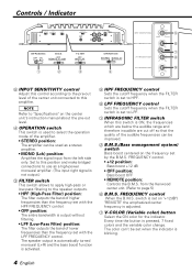
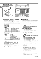
...The speaker output is automatically turned monaural (L+R) and the bass boost function is activated. 9 HPF FREQUENCY control Sets the cutoff frequency when the FILTER switch is set to HPF. 8 LPF FREQUENCY control Sets the cutoff frequency when the FILTER switch is adjusted. 7 V-COLOR (Variable color) button Select the ON color for the indicator. L L R R INFRASONIC OFF ON B.M.S. FREQUENCY control When the B.M.S. switch is set on the center unit's instruction manual about the pre-out level. 4 OPERATION switch This switch is used as a high-power monaural amplifier. (The input right...
...The speaker output is automatically turned monaural (L+R) and the bass boost function is activated. 9 HPF FREQUENCY control Sets the cutoff frequency when the FILTER switch is set to HPF. 8 LPF FREQUENCY control Sets the cutoff frequency when the FILTER switch is adjusted. 7 V-COLOR (Variable color) button Select the ON color for the indicator. L L R R INFRASONIC OFF ON B.M.S. FREQUENCY control When the B.M.S. switch is set on the center unit's instruction manual about the pre-out level. 4 OPERATION switch This switch is used as a high-power monaural amplifier. (The input right...
Instruction Manual
Page 5
FREQUENCY control adjustment value. NOTE Turn the power OFF and release the protection. When the speaker cord is 20- 30% low. There may be selected with the vehicle ground. If the indicator doesn't quit blinking, contact your Kenwood dealer. • The color blinks red When the inside of the below times. - from the center unit. • Bass boost Center unit display Setting "Flat"/ "OFF"/ "1" Bass boost OFF (Flat) "+6"/ "1"/ "2" Bass boost +6 dB "+12"/ "2"/ "3" Bass boost +12 dB...
FREQUENCY control adjustment value. NOTE Turn the power OFF and release the protection. When the speaker cord is 20- 30% low. There may be selected with the vehicle ground. If the indicator doesn't quit blinking, contact your Kenwood dealer. • The color blinks red When the inside of the below times. - from the center unit. • Bass boost Center unit display Setting "Flat"/ "OFF"/ "1" Bass boost OFF (Flat) "+6"/ "1"/ "2" Bass boost +6 dB "+12"/ "2"/ "3" Bass boost +12 dB...
Instruction Manual
Page 6
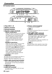
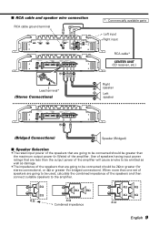
... 3 power amplifiers can be possible due to be connected, ensure that 's input from the line input terminal is 2Ω or greater for each channel. • Bridged Connections: When you wish to use the unit as a stereo amplifier, stereo connections are used. (Make connections to the LEFT channel 9 and the RIGHT channel · SPEAKER OUTPUT terminals.) The speakers to wiring wire type and length. L L R R ^ &* ( ! Otherwise malfunction may not be used . When multiple speakers are cases when operation may result. ^ RCA cable ground lead terminal...
... 3 power amplifiers can be possible due to be connected, ensure that 's input from the line input terminal is 2Ω or greater for each channel. • Bridged Connections: When you wish to use the unit as a stereo amplifier, stereo connections are used. (Make connections to the LEFT channel 9 and the RIGHT channel · SPEAKER OUTPUT terminals.) The speakers to wiring wire type and length. L L R R ^ &* ( ! Otherwise malfunction may not be used . When multiple speakers are cases when operation may result. ^ RCA cable ground lead terminal...
Instruction Manual
Page 7
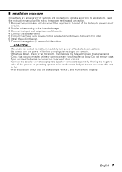
... connection. 1. terminal of the battery. 2CAUTION • If sound is not output normally, immediately turn power off and check connections. • Be sure to turn the power off before changing the setting of any switch. • If the fuse blows, check wires for shorts, then replace the fuse with one of settings and connections possible according to applications, read the instruction manual well to prevent short circuits. 2. Sharing the negative wire of the speaker...
... connection. 1. terminal of the battery. 2CAUTION • If sound is not output normally, immediately turn power off and check connections. • Be sure to turn the power off before changing the setting of any switch. • If the fuse blows, check wires for shorts, then replace the fuse with one of settings and connections possible according to applications, read the instruction manual well to prevent short circuits. 2. Sharing the negative wire of the speaker...
Instruction Manual
Page 8
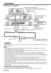
... B.M.S. Power control wire (Blue/ White) Protective Fuse* Battery * : Commercially available parts 2WARNING To prevent fire caused by using Grommets. • Connect the ground wire to a metal part of wire for this unit directly from the end. 2. OFF REMOTE +12dB FILTER OFF HPF LPF ( OPERATION STEREO MONO(L ch) GND LINE IN LINE OUT EXT.AMP.CONT. EXT.AMP.CONT. (external amplifier control) terminal ( 1. Wiring •Take the battery wire for a length of 8 mm2 (AWG 8) or greater.) • When more than the unit's fuse capacity. (Use a power wiring...
... B.M.S. Power control wire (Blue/ White) Protective Fuse* Battery * : Commercially available parts 2WARNING To prevent fire caused by using Grommets. • Connect the ground wire to a metal part of wire for this unit directly from the end. 2. OFF REMOTE +12dB FILTER OFF HPF LPF ( OPERATION STEREO MONO(L ch) GND LINE IN LINE OUT EXT.AMP.CONT. EXT.AMP.CONT. (external amplifier control) terminal ( 1. Wiring •Take the battery wire for a length of 8 mm2 (AWG 8) or greater.) • When more than the unit's fuse capacity. (Use a power wiring...
Instruction Manual
Page 9
... greater than the output power of the amplifier will cause smoke to be emitted as well as damage. • The impedance of the speakers and then connect suitable speakers to be 2Ω or greater (for stereo connections), or 4Ω or greater (for bridged connections). ■ RCA cable and speaker wire connection RCA cable ground terminal ^& INFRASONIC OFF ON B.M.S. OFF REMOTE +12dB FILTER OFF HPF LPF OPERATION STEREO MONO(L ch) GND LINE IN LINE OUT EXT.AMP.CONT.
... greater than the output power of the amplifier will cause smoke to be emitted as well as damage. • The impedance of the speakers and then connect suitable speakers to be 2Ω or greater (for stereo connections), or 4Ω or greater (for bridged connections). ■ RCA cable and speaker wire connection RCA cable ground terminal ^& INFRASONIC OFF ON B.M.S. OFF REMOTE +12dB FILTER OFF HPF LPF OPERATION STEREO MONO(L ch) GND LINE IN LINE OUT EXT.AMP.CONT.
Instruction Manual
Page 10
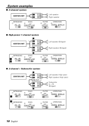
...+12dB FILTER 3 OFF HPF LPF OPERATION 4 STEREO MONO(L ch) ■ High-power 1-channel system CENTER UNIT ¡ L L L RR Left speaker (Bridged) RL R ™ INFRASONIC 1 ¡ OFF ON ™ B.M.S. 2 OFF REMOTE +12dB L Right speaker (Bridged) R FILTER 3 OFF HPF LPF OPERATION 4 STEREO MONO(L ch) ■ 2-channel + Subwoofer system CENTER UNIT ¡ L L RR LINE OUT L L RR ™ Left speaker (High pass) Right speaker (High pass) Subwoofer (L + R) (Bridged) INFRASONIC 1 OFF ON ¡ B.M.S. 2 OFF REMOTE +12dB FILTER 3 OFF HPF LPF OPERATION 4 STEREO MONO(L ch...
...+12dB FILTER 3 OFF HPF LPF OPERATION 4 STEREO MONO(L ch) ■ High-power 1-channel system CENTER UNIT ¡ L L L RR Left speaker (Bridged) RL R ™ INFRASONIC 1 ¡ OFF ON ™ B.M.S. 2 OFF REMOTE +12dB L Right speaker (Bridged) R FILTER 3 OFF HPF LPF OPERATION 4 STEREO MONO(L ch) ■ 2-channel + Subwoofer system CENTER UNIT ¡ L L RR LINE OUT L L RR ™ Left speaker (High pass) Right speaker (High pass) Subwoofer (L + R) (Bridged) INFRASONIC 1 OFF ON ¡ B.M.S. 2 OFF REMOTE +12dB FILTER 3 OFF HPF LPF OPERATION 4 STEREO MONO(L ch...
Instruction Manual
Page 11
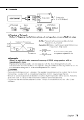
... wish to bridge-connect a speaker, the speaker impedance must be passed. ■ Tri-mode CENTER UNIT L L RR L C (High pass) C Subwoofer (L + R) (Bridged) INFRASONIC B.M.S. 1 2 OFF ON OFF REMOTE +12dB FILTER 3 OFF HPF LPF OPERATION 4 STEREO MONO(L ch) ●Principle of Tri-mode Method of frequency band division using speakers with an impedance of 4 ohms. Prepare commercially-available coil and capacitor with the subwoofer. • Ensure that the withstand voltage and current ratings of...
... wish to bridge-connect a speaker, the speaker impedance must be passed. ■ Tri-mode CENTER UNIT L L RR L C (High pass) C Subwoofer (L + R) (Bridged) INFRASONIC B.M.S. 1 2 OFF ON OFF REMOTE +12dB FILTER 3 OFF HPF LPF OPERATION 4 STEREO MONO(L ch) ●Principle of Tri-mode Method of frequency band division using speakers with an impedance of 4 ohms. Prepare commercially-available coil and capacitor with the subwoofer. • Ensure that the withstand voltage and current ratings of...
Instruction Manual
Page 12
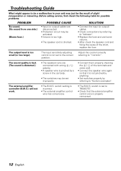
...; The external amplifier control wire has come loose. • The B.M.S. switch setting is too small (or too large). switch is set to "REMOTE". • Check that it is shorted. • Connect the input (or output) cables. • Check connections by a screw in your unit may just be the result of the short, replace the fuse. The external amplifier controller (B.M.S.) will not work. • The B.M.S. Adjust the control correctly referring to "Controls". Troubleshooting Guide What might...
...; The external amplifier control wire has come loose. • The B.M.S. switch setting is too small (or too large). switch is set to "REMOTE". • Check that it is shorted. • Connect the input (or output) cables. • Check connections by a screw in your unit may just be the result of the short, replace the fuse. The external amplifier controller (B.M.S.) will not work. • The B.M.S. Adjust the control correctly referring to "Controls". Troubleshooting Guide What might...
Instruction Manual
Page 13
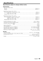
... dB # Sensitivity = MIN. , Through LPF (30 kHz) General Operating Voltage 12.0 V (11 - 16 V allowable) Current Consumption (+B = 12.0 V, 4 Ω, 10 % THD 37 A Dimensions (W × H × D 283 × 58 × 350 mm ...11-1/3 × 2-5/16 × 13-3/4 inch Weight ...5.2 kg (11.5 lbs) English 13 Audio Section Max Power Output (4 Ω) Normal...500 W × 2 Bridged ...1000 W × 1 Rated Power Output (+B = 12.0 V) Normal (4 Ω...
... dB # Sensitivity = MIN. , Through LPF (30 kHz) General Operating Voltage 12.0 V (11 - 16 V allowable) Current Consumption (+B = 12.0 V, 4 Ω, 10 % THD 37 A Dimensions (W × H × D 283 × 58 × 350 mm ...11-1/3 × 2-5/16 × 13-3/4 inch Weight ...5.2 kg (11.5 lbs) English 13 Audio Section Max Power Output (4 Ω) Normal...500 W × 2 Bridged ...1000 W × 1 Rated Power Output (+B = 12.0 V) Normal (4 Ω...


