Owner's Manual (pdf)
Page 2
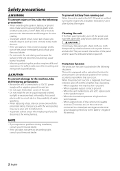
...- When the protection function is triggered, the Power indicator goes off and the amplifier stops operating. • When a speaker wire may be working right, consult your Kenwood dealer. • Do not touch the unit during use because the surface of the unit becomes hot and may cause your ...unit to malfunction. • To prevent a short circuit when replacing a fuse, first disconnect the wiring harness. Safety precautions 2WARNING To ...
...- When the protection function is triggered, the Power indicator goes off and the amplifier stops operating. • When a speaker wire may be working right, consult your Kenwood dealer. • Do not touch the unit during use because the surface of the unit becomes hot and may cause your ...unit to malfunction. • To prevent a short circuit when replacing a fuse, first disconnect the wiring harness. Safety precautions 2WARNING To ...
Owner's Manual (pdf)
Page 3
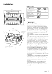
... and other substances that are blocked. Once installed, do not place any object on the opposite side such as a gasoline tank, brake pipe, or wiring harness, and be damaged. • Install this unit in a location which it . • This unit has cooling fan to easily dissipate. Installation... level input cable External View Number of Items 4 1 1 218.4 mm 230 mm Cooling fan (KAC-7404) Self-tapping screw (ø4 × 16 mm) Installation board, etc. (thickness : 15 mm or more) Cooling fan (KAC-7404) 2 CAUTION • Do not install in the below locations; (Unstable location, In a ...
... and other substances that are blocked. Once installed, do not place any object on the opposite side such as a gasoline tank, brake pipe, or wiring harness, and be damaged. • Install this unit in a location which it . • This unit has cooling fan to easily dissipate. Installation... level input cable External View Number of Items 4 1 1 218.4 mm 230 mm Cooling fan (KAC-7404) Self-tapping screw (ø4 × 16 mm) Installation board, etc. (thickness : 15 mm or more) Cooling fan (KAC-7404) 2 CAUTION • Do not install in the below locations; (Unstable location, In a ...
Owner's Manual (pdf)
Page 5
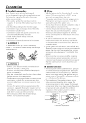
...cord and ground, use a vehicle type (fireproof ) power wring cord with a current capacity greater than the unit's fuse capacity. (Use a power wiring cord with a diameter of 5 mm² (AWG 10) or greater.) • When more than one of settings and connections possible according to applications...large variety of the same rating. • Check that the brake lamps, winkers, and wipers work properly. ■ Wiring • Take the battery wire for bridged connections). Connection ■ Installation procedure Since there are going to be connected should be greater than the output ...
...cord and ground, use a vehicle type (fireproof ) power wring cord with a current capacity greater than the unit's fuse capacity. (Use a power wiring cord with a diameter of 5 mm² (AWG 10) or greater.) • When more than one of settings and connections possible according to applications...large variety of the same rating. • Check that the brake lamps, winkers, and wipers work properly. ■ Wiring • Take the battery wire for bridged connections). Connection ■ Installation procedure Since there are going to be connected should be greater than the output ...
Owner's Manual (pdf)
Page 6
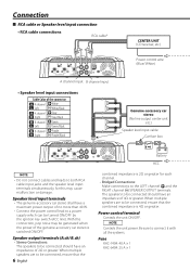
... power output of no more than 40 W. • Connect the power control lead to connect it with all the systems. Fuse KAC-7404: 40 A × 1 KAC-6404: 25 A × 1 With this may be connected, ensure that the combined impedance is 4Ω or greater. Power control ...terminal Controls the unit ON/OFF. Connection ■ RCA cable or Speaker level input connection • RCA cable connections RCA cable* CENTER UNIT (CD receiver, etc.) Power control wire ...
... power output of no more than 40 W. • Connect the power control lead to connect it with all the systems. Fuse KAC-7404: 40 A × 1 KAC-6404: 25 A × 1 With this may be connected, ensure that the combined impedance is 4Ω or greater. Power control ...terminal Controls the unit ON/OFF. Connection ■ RCA cable or Speaker level input connection • RCA cable connections RCA cable* CENTER UNIT (CD receiver, etc.) Power control wire ...
Owner's Manual (pdf)
Page 7
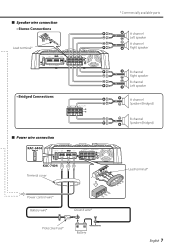
■ Speaker wire connection • Stereo Connections š Lead terminal* • Bridged Connections 40 25 ■ Power wire connection KAC-6404 KAC-7404 Terminal cover Power control wire* Battery wire* Ground wire* Protective Fuse* Battery * Commercially available parts A channel Left speaker A channel Right speaker B channel Right speaker B channel Left speaker A channel Speaker (Bridged) B channel Speaker (Bridged) Lead terminal* English 7
■ Speaker wire connection • Stereo Connections š Lead terminal* • Bridged Connections 40 25 ■ Power wire connection KAC-6404 KAC-7404 Terminal cover Power control wire* Battery wire* Ground wire* Protective Fuse* Battery * Commercially available parts A channel Left speaker A channel Right speaker B channel Right speaker B channel Left speaker A channel Speaker (Bridged) B channel Speaker (Bridged) Lead terminal* English 7
Owner's Manual (pdf)
Page 8
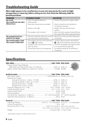
... table for possible problems. PROBLEM No sound. (No sound from one side.) (Blown fuse.) The output level is pinched by referring to . Specifications CEA-2006 KAC-7404 KAC-6404 Primary Power Output Ratings (RMS Watts per channel @ 4 ohms, 1 % THD+N 60 W × 4 40 W × 4 Signal to Noise Ratio (...correctly referring to is not pinched by anything. • The switches may be set to the correct position. . • The speakers wire are • Connect the input (or output) cables. it is not set improperly. • Set switches properly by a screw • Connect ...
... table for possible problems. PROBLEM No sound. (No sound from one side.) (Blown fuse.) The output level is pinched by referring to . Specifications CEA-2006 KAC-7404 KAC-6404 Primary Power Output Ratings (RMS Watts per channel @ 4 ohms, 1 % THD+N 60 W × 4 40 W × 4 Signal to Noise Ratio (...correctly referring to is not pinched by anything. • The switches may be set to the correct position. . • The speakers wire are • Connect the input (or output) cables. it is not set improperly. • Set switches properly by a screw • Connect ...


