Instruction Manual
Page 2
...: • Be sure the unit is connected to a 12V DC power supply with a negative ground connection. • Do not open the top or bottom covers of the unit. • Do not install the unit in the unit to protect the unit and speakers from various problems. When Protection operates, the indicator informs you experience problems during use because the surface of Items 4 Terminal cover (Power terminal) 1 Speaker level input cable 1 2 English Use it depletes the battery.
...: • Be sure the unit is connected to a 12V DC power supply with a negative ground connection. • Do not open the top or bottom covers of the unit. • Do not install the unit in the unit to protect the unit and speakers from various problems. When Protection operates, the indicator informs you experience problems during use because the surface of Items 4 Terminal cover (Power terminal) 1 Speaker level input cable 1 2 English Use it depletes the battery.
Instruction Manual
Page 3
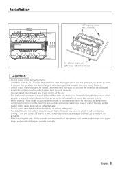
...wiring harness, and be careful not to cause scratches or other substances that are sensitive to easily dissipate. If the unit comes off due to a shock and hits a person or safety part, it . • When making a hole under the carpet. Otherwise heat build-up occurs and the unit may be damaged. • Install this unit... installing the unit, check to make sure that there is nothing hazardous on top of the unit. • The surface temperature of the amplifier will become hot during use. Once installed, do not place any object on the opposite side such as the brake lamps, turn signal...
...wiring harness, and be careful not to cause scratches or other substances that are sensitive to easily dissipate. If the unit comes off due to a shock and hits a person or safety part, it . • When making a hole under the carpet. Otherwise heat build-up occurs and the unit may be damaged. • Install this unit... installing the unit, check to make sure that there is nothing hazardous on top of the unit. • The surface temperature of the amplifier will become hot during use. Once installed, do not place any object on the opposite side such as the brake lamps, turn signal...
Instruction Manual
Page 4
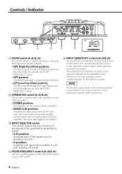
... pre-output level or the maximum power output, refer to the in the instruction manual of the center unit. 4 English Set to this position and make bridged connections to use as a stereo amplifier. • MONO (Lch) position: Amplifies the signal input from the left side only. Controls / Indicator 5 40 30 20 10 (W) 1 2 3 4 5 1 FILTER switch (A.ch/B.ch) This switch allows to apply high-pass or low-pass filtering to the speaker outputs. • HPF (High-Pass Filter) position: The filter outputs...
... pre-output level or the maximum power output, refer to the in the instruction manual of the center unit. 4 English Set to this position and make bridged connections to use as a stereo amplifier. • MONO (Lch) position: Amplifies the signal input from the left side only. Controls / Indicator 5 40 30 20 10 (W) 1 2 3 4 5 1 FILTER switch (A.ch/B.ch) This switch allows to apply high-pass or low-pass filtering to the speaker outputs. • HPF (High-Pass Filter) position: The filter outputs...
Instruction Manual
Page 5
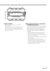
... battery's negative - 6 6 Power indicator When the power is not connected to a metal part serving as an electrical ground passing electricity to the speaker output. • When the internal temperature is turned on , the Power indicator lights. If the Power indicator does not light when the power is high and unit won't operate. • When a ground wire of trouble. ■ The protection function is activated in the following situations: This unit is equipped with a protection function for protecting this unit...
... battery's negative - 6 6 Power indicator When the power is not connected to a metal part serving as an electrical ground passing electricity to the speaker output. • When the internal temperature is turned on , the Power indicator lights. If the Power indicator does not light when the power is high and unit won't operate. • When a ground wire of trouble. ■ The protection function is activated in the following situations: This unit is equipped with a protection function for protecting this unit...
Instruction Manual
Page 6
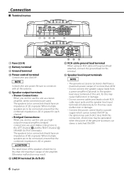
... the power of the genuine-accessory car stereo is 4Ω or greater. 2CAUTION The rated input of the speakers should have an impedance of the amplifier. Speaker output terminals • Stereo Connections: When you wish to use the unit as a highoutput monaural amplifier, bridged connections are to be connected should be turned ON/OFF by the ignition key switch (ACC line). Connection ■ Terminal names 7 8 90 ! 7 Fuse (25 A) 8 Battery terminal 9 Ground terminal 0 Power control terminal Controls the unit ON/OFF. When multiple speakers are used .
... the power of the genuine-accessory car stereo is 4Ω or greater. 2CAUTION The rated input of the speakers should have an impedance of the amplifier. Speaker output terminals • Stereo Connections: When you wish to use the unit as a highoutput monaural amplifier, bridged connections are to be connected should be turned ON/OFF by the ignition key switch (ACC line). Connection ■ Terminal names 7 8 90 ! 7 Fuse (25 A) 8 Battery terminal 9 Ground terminal 0 Power control terminal Controls the unit ON/OFF. When multiple speakers are used .
Instruction Manual
Page 7
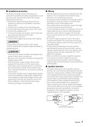
... wipers work properly. ■ Wiring • Take the battery wire for bridged connections). terminal. Use of speakers having input power ratings that are less than the maximum output power (in the wiring, connect a fusible link or breaker nearby the battery's positive terminal. 2CAUTION • If sound is not output normally, immediately turn power off and check connections. • Be sure to turn the power on if the ground wire is running, connect a line noise filter (optional) to each of the battery wire...
... wipers work properly. ■ Wiring • Take the battery wire for bridged connections). terminal. Use of speakers having input power ratings that are less than the maximum output power (in the wiring, connect a fusible link or breaker nearby the battery's positive terminal. 2CAUTION • If sound is not output normally, immediately turn power off and check connections. • Be sure to turn the power on if the ground wire is running, connect a line noise filter (optional) to each of the battery wire...
Instruction Manual
Page 8
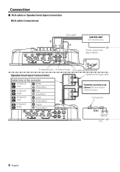
Connection ■ RCA cable or Speaker level input connection (RCA cable Connections) RCA cable* CENTER UNIT @ (CD receiver, etc.) # Power control wire (Blue/ White) # GND A channel input B channel input RCA cable ground terminal (Speaker level input Connections) Speaker level input cable Cable Color of the connector A channel Left White White/Black A channel Right Gray Gray/Black B channel Green Left Green/Black $ B channel Right Purple Purple/Black Genuine-accessory car stereo (No line output center unit etc.) Car fuse box Battery ACC 8 English
Connection ■ RCA cable or Speaker level input connection (RCA cable Connections) RCA cable* CENTER UNIT @ (CD receiver, etc.) # Power control wire (Blue/ White) # GND A channel input B channel input RCA cable ground terminal (Speaker level input Connections) Speaker level input cable Cable Color of the connector A channel Left White White/Black A channel Right Gray Gray/Black B channel Green Left Green/Black $ B channel Right Purple Purple/Black Genuine-accessory car stereo (No line output center unit etc.) Car fuse box Battery ACC 8 English
Instruction Manual
Page 9
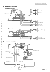
Lead terminal* 25 (Bridged Connections) ! 25 ■ Power wire connection 25 Terminal cover 8 90 Power control wire Battery wire* Ground wire* Protective Fuse* Battery * Commercially available parts A channel Left speaker A channel Right speaker B channel Right speaker B channel Left speaker A channel Speaker (Bridged) B channel Speaker (Bridged) Lead terminal* English 9 ■ Speaker wire connection (Stereo Connections) ! !
Lead terminal* 25 (Bridged Connections) ! 25 ■ Power wire connection 25 Terminal cover 8 90 Power control wire Battery wire* Ground wire* Protective Fuse* Battery * Commercially available parts A channel Left speaker A channel Right speaker B channel Right speaker B channel Left speaker A channel Speaker (Bridged) B channel Speaker (Bridged) Lead terminal* English 9 ■ Speaker wire connection (Stereo Connections) ! !
Instruction Manual
Page 11
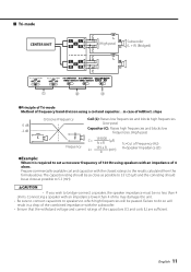
... connect capacitors to speakers to which high frequencies will result in case of 6dB/oct. Failure to do so will be passed. ■ Tri-mode CENTER UNIT L L A RR L L B RR C L (High pass) C C L C Subwoofer (L + R) (Bridged) 1 2 3 ●Principle of Tri-mode Method of frequency band division using speakers with an impedance of 4 ohms. Prepare commercially-available coil and capacitor with an impedance lower than 4 ohms. Connecting a speaker with the closest ratings...
... connect capacitors to speakers to which high frequencies will result in case of 6dB/oct. Failure to do so will be passed. ■ Tri-mode CENTER UNIT L L A RR L L B RR C L (High pass) C C L C Subwoofer (L + R) (Bridged) 1 2 3 ●Principle of Tri-mode Method of frequency band division using speakers with an impedance of 4 ohms. Prepare commercially-available coil and capacitor with an impedance lower than 4 ohms. Connecting a speaker with the closest ratings...
Instruction Manual
Page 12
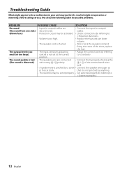
The output level is distorted.) with wrong + /-polarity. + / - of the terminals and wires well. • A speaker wire is pinched by a screw • Connect the speaker wire again so in your unit may just be set to the correct to . 12 English cables. (Blown fuse.) • Protection circuit may be the result of the short, replace the fuse. position. Troubleshooting Guide What might appear to . • Volume is too high. • Replace the fuse and use lower volume. •...
The output level is distorted.) with wrong + /-polarity. + / - of the terminals and wires well. • A speaker wire is pinched by a screw • Connect the speaker wire again so in your unit may just be set to the correct to . 12 English cables. (Blown fuse.) • Protection circuit may be the result of the short, replace the fuse. position. Troubleshooting Guide What might appear to . • Volume is too high. • Replace the fuse and use lower volume. •...
Instruction Manual
Page 13
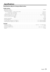
Specifications Specifications subject to Noise Ratio...100 dB Input Impedance...10 kΩ Low Pass Filter Frequency (12 dB/oct.) ...50 - 200 Hz (variable) High Pass Filter Frequency (12 dB/oct.)...50 - 200 Hz (variable) General Operating Voltage...14.4 V (11 - 16 V allowable) Current Consumption ...25 A Dimensions (W x H x D)...330 x 59 x 242 mm Weight...3.0 kg English 13 Audio Section Max Power Output ...400 W Rated Power Output Normal (4 Ω) (20 Hz - 20...
Specifications Specifications subject to Noise Ratio...100 dB Input Impedance...10 kΩ Low Pass Filter Frequency (12 dB/oct.) ...50 - 200 Hz (variable) High Pass Filter Frequency (12 dB/oct.)...50 - 200 Hz (variable) General Operating Voltage...14.4 V (11 - 16 V allowable) Current Consumption ...25 A Dimensions (W x H x D)...330 x 59 x 242 mm Weight...3.0 kg English 13 Audio Section Max Power Output ...400 W Rated Power Output Normal (4 Ω) (20 Hz - 20...


