Instruction Manual
Page 3
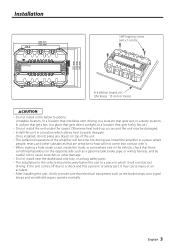
...harness, and be damaged. • Install this unit in which allows heat to a place in a location which it will not obstruct driving. Install the amplifier in a place where people, resins, and other substances that are sensitive to heat will not come into contact with driving, In a location that gets ...the trunk, or somewhere else in the vehicle, check that there is nothing hazardous on top of the unit. • The surface temperature of the amplifier will become hot during use. Installation Ø4.6 330 mm 231 mm Self-tapping screw (ø4 × 16 mm) 227 mm 232 mm 242 ...
...harness, and be damaged. • Install this unit in which allows heat to a place in a location which it will not obstruct driving. Install the amplifier in a place where people, resins, and other substances that are sensitive to heat will not come into contact with driving, In a location that gets ...the trunk, or somewhere else in the vehicle, check that there is nothing hazardous on top of the unit. • The surface temperature of the amplifier will become hot during use. Installation Ø4.6 330 mm 231 mm Self-tapping screw (ø4 × 16 mm) 227 mm 232 mm 242 ...
Instruction Manual
Page 4
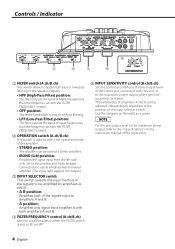
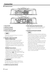
... from the left side only. Set to this position and make bridged connections to use as a high-power monaural amplifier. (The input right signal is not output.) 3 INPUT SELECTOR switch This switch selects the input method of the signals... B can be used to select the operation mode of the amplifier. • STEREO position: The amplifier can be amplified by amplifiers A and B. • A B position: Amplifies both of the signals input to amplifiers A and B. • A position: Amplifies only signal input amplifier A with both amplifiers A and B. 4 FILTER FREQUENCY control (A.ch/B.ch) Sets the...
... from the left side only. Set to this position and make bridged connections to use as a high-power monaural amplifier. (The input right signal is not output.) 3 INPUT SELECTOR switch This switch selects the input method of the signals... B can be used to select the operation mode of the amplifier. • STEREO position: The amplifier can be amplified by amplifiers A and B. • A B position: Amplifies both of the signals input to amplifiers A and B. • A position: Amplifies only signal input amplifier A with both amplifiers A and B. 4 FILTER FREQUENCY control (A.ch/B.ch) Sets the...
Instruction Manual
Page 5
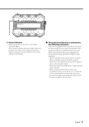
... not light when the power is turned on , the Power indicator lights. When the protection function is triggered, the Power indicator goes off and the amplifier stops operating. • When a speaker wire may be short-circuited. • When a speaker output contacts ground. • When the unit malfunctions and a DC signal is...
... not light when the power is turned on , the Power indicator lights. When the protection function is triggered, the Power indicator goes off and the amplifier stops operating. • When a speaker wire may be short-circuited. • When a speaker output contacts ground. • When the unit malfunctions and a DC signal is...
Instruction Manual
Page 6
...more than the maximum output of this unit, for each channel. • Bridged Connections: When you wish to use the unit as a stereo amplifier, stereo connections are used . When multiple speakers are to be connected, ensure that the combined impedance is 4Ω or greater. 2CAUTION The ...8486; or greater for this may cause malfunction or damage. • Do not connect cables and leads to use the unit as a highoutput monaural amplifier, bridged connections are used . (Make connections to the LEFT channel 9 and the RIGHT channel · SPEAKER OUTPUT terminals.) The speakers to be...
...more than the maximum output of this unit, for each channel. • Bridged Connections: When you wish to use the unit as a stereo amplifier, stereo connections are used . When multiple speakers are to be connected, ensure that the combined impedance is 4Ω or greater. 2CAUTION The ...8486; or greater for this may cause malfunction or damage. • Do not connect cables and leads to use the unit as a highoutput monaural amplifier, bridged connections are used . (Make connections to the LEFT channel 9 and the RIGHT channel · SPEAKER OUTPUT terminals.) The speakers to be...
Instruction Manual
Page 7
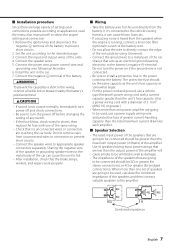
...power off before changing the setting of any switch. • If the fuse blows, check wires for bridged connections). Set the unit according to the amplifier. 4Ω 4Ω 8 Ω 4Ω 4Ω 2 Ω Combined impedance English 7 terminal of the battery. 2WARNING To prevent fire... (AWG 10) or greater.) • When more than the unit's fuse capacity. (Use a power wiring cord with one set of the amplifier. Remove the ignition key and disconnect the negative - ■ Installation procedure Since there are large variety of the units. 4. Connect the speaker ...
...power off before changing the setting of any switch. • If the fuse blows, check wires for bridged connections). Set the unit according to the amplifier. 4Ω 4Ω 8 Ω 4Ω 4Ω 2 Ω Combined impedance English 7 terminal of the battery. 2WARNING To prevent fire... (AWG 10) or greater.) • When more than the unit's fuse capacity. (Use a power wiring cord with one set of the amplifier. Remove the ignition key and disconnect the negative - ■ Installation procedure Since there are large variety of the units. 4. Connect the speaker ...


