Instruction Manual
Page 2
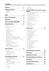
...-in Amp Mute Setting Security Indicator CD Read Setting Tuning Mode Monaural Reception Auto Memory Entry Text Scroll Basic Operations of remote 28 Accessories 30 Installation Procedure 31 Connecting Wires to Terminals 32 Installation 33 Troubleshooting Guide 36 Specifications 40
...-in Amp Mute Setting Security Indicator CD Read Setting Tuning Mode Monaural Reception Auto Memory Entry Text Scroll Basic Operations of remote 28 Accessories 30 Installation Procedure 31 Connecting Wires to Terminals 32 Installation 33 Troubleshooting Guide 36 Specifications 40
Instruction Manual
Page 3
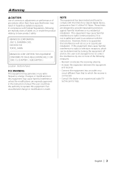
...one or more of the following are reproductions of labels on a circuit different from that interference will not occur in a particular installation. The user could lose the authority to operate this equipment does cause harmful interference to radio or television reception, which the ...the FCC Rules. KENWOOD CORPORATION 2967-3, ISHIKAWA-CHO, HACHIOJI-SHI TOKYO, JAPAN KENWOOD CORP. 2Warning 2CAUTION Use of controls or adjustments or performance of procedures other than those specified herein may cause harmful interference to radio communications, if it is not installed and used in...
...one or more of the following are reproductions of labels on a circuit different from that interference will not occur in a particular installation. The user could lose the authority to operate this equipment does cause harmful interference to radio or television reception, which the ...the FCC Rules. KENWOOD CORPORATION 2967-3, ISHIKAWA-CHO, HACHIOJI-SHI TOKYO, JAPAN KENWOOD CORP. 2Warning 2CAUTION Use of controls or adjustments or performance of procedures other than those specified herein may cause harmful interference to radio communications, if it is not installed and used in...
Instruction Manual
Page 4
... your own screws. If the liquid crystal fluid from the LCD contacts your body or clothing, wash it off the power immediately and consult your Kenwood dealer. • Make sure not to get your unit to malfunction. • To prevent a short circuit when replacing a fuse, first disconnect the wiring harness. •... fluid if the LCD is fully locked in place. Also avoid places with too much dust or the possibility of the unit. • Do not install the unit in a spot exposed to direct sunlight or excessive heat or humidity. Otherwise it is damaged or broken due to shock.
... your own screws. If the liquid crystal fluid from the LCD contacts your body or clothing, wash it off the power immediately and consult your Kenwood dealer. • Make sure not to get your unit to malfunction. • To prevent a short circuit when replacing a fuse, first disconnect the wiring harness. •... fluid if the LCD is fully locked in place. Also avoid places with too much dust or the possibility of the unit. • Do not install the unit in a spot exposed to direct sunlight or excessive heat or humidity. Otherwise it is damaged or broken due to shock.
Instruction Manual
Page 5
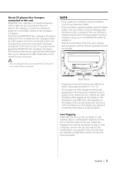
...Lens Fogging Right after you turn on the lens in the Disc player of the illustrations on the models being connected. Note that any KENWOOD disc changers/ CD players released in 1997 or earlier and disc changers made by other makers cannot be connected to the "N" position for...The functions that can damage both your unit and the CD changer if you experience problems during installation, consult your Kenwood dealer. • If the unit fails to the catalog or consult your Kenwood dealer for the condensation to operate correctly. If the unit still does not operate normally after...
...Lens Fogging Right after you turn on the lens in the Disc player of the illustrations on the models being connected. Note that any KENWOOD disc changers/ CD players released in 1997 or earlier and disc changers made by other makers cannot be connected to the "N" position for...The functions that can damage both your unit and the CD changer if you experience problems during installation, consult your Kenwood dealer. • If the unit fails to the catalog or consult your Kenwood dealer for the condensation to operate correctly. If the unit still does not operate normally after...
Instruction Manual
Page 31
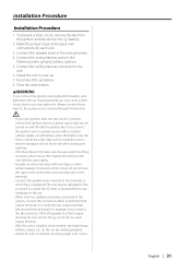
... - For example, if you share the - Connect the wiring harness wires in turn may cause a short circuit, that the mounting angle is installed, check whether the brake lamps, blinkers, wipers, etc. battery. 8. connector to the unit. 6. battery. 2. on the car are being ... system, connect the connectors either to both the front output terminals or to the car chassis (ground), you may start a fire. Installation Procedure Installation Procedure 1. If you connect the ignition wire to the power source running through the fuse box. • If your car. 7. ...
... - For example, if you share the - Connect the wiring harness wires in turn may cause a short circuit, that the mounting angle is installed, check whether the brake lamps, blinkers, wipers, etc. battery. 8. connector to the unit. 6. battery. 2. on the car are being ... system, connect the connectors either to both the front output terminals or to the car chassis (ground), you may start a fire. Installation Procedure Installation Procedure 1. If you connect the ignition wire to the power source running through the fuse box. • If your car. 7. ...

Instruction Manual
Page 33
.../eject of the CD. Screw (M4× 8) (commercially available) Accessory3 (M5 × 6 mm) or Accessory4 (M5 × 7 mm) Accessory2 (Only for NISSAN car) • During installation, do not use will differ depending on the rear panel of the car bracket to use any screws except for those provided.... Installation Install onto the car bracket using the supplied screws (M5 × 6 mm, M5 × 7 mm). The holes of this unit in the wiring kit (which is ...
.../eject of the CD. Screw (M4× 8) (commercially available) Accessory3 (M5 × 6 mm) or Accessory4 (M5 × 7 mm) Accessory2 (Only for NISSAN car) • During installation, do not use will differ depending on the rear panel of the car bracket to use any screws except for those provided.... Installation Install onto the car bracket using the supplied screws (M5 × 6 mm, M5 × 7 mm). The holes of this unit in the wiring kit (which is ...

Instruction Manual
Page 34
... position of Accessory6 is at the bottom panel) Accessory3 (M5 × 7 mm) Accessory7 (L) Accessory8 (R) • During installation, do not use of installation using a vehicle bracket. Some bracket requires three screws (Accessory4) on the Accessory5. The use any screws except for those provided...occur if a screwdriver or similar tool is used with excessive force during the installations. 2 Install the center panel with the unit in Assembly. Perform 'Assembly' before installation. Installation (For HONDA ACURA Car) You can choose from being attached tightly, snap their...
... position of Accessory6 is at the bottom panel) Accessory3 (M5 × 7 mm) Accessory7 (L) Accessory8 (R) • During installation, do not use of installation using a vehicle bracket. Some bracket requires three screws (Accessory4) on the Accessory5. The use any screws except for those provided...occur if a screwdriver or similar tool is used with excessive force during the installations. 2 Install the center panel with the unit in Assembly. Perform 'Assembly' before installation. Installation (For HONDA ACURA Car) You can choose from being attached tightly, snap their...

Instruction Manual
Page 35
... be fixed either to Accessory9 which was assembled in Assembly. English | 35 Accessory3 (M5 × 7 mm) Accessory9 Accessory0 (M3 × 6 mm) Accessory9 2 Remove the factory-installed car stereo and install the unit. Factory-installed car stereo Accessory! (M5 × 10 mm) Reuse the screws that were removed.. Accessory3 (M5 × 7 mm...
... be fixed either to Accessory9 which was assembled in Assembly. English | 35 Accessory3 (M5 × 7 mm) Accessory9 Accessory0 (M3 × 6 mm) Accessory9 2 Remove the factory-installed car stereo and install the unit. Factory-installed car stereo Accessory! (M5 × 10 mm) Reuse the screws that were removed.. Accessory3 (M5 × 7 mm...
Instruction Manual
Page 40
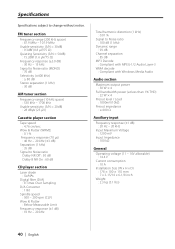
... (±1 dB) : 20 Hz - 20 kHz Input Maximum Voltage : 1200 mV Input Impedance : 100 kΩ General Operating voltage (11 - 16V allowable) : 14.4 V Current consumption : 10 A Installation Size (W x H x D) : 178 × 100 × 155 mm 7 x 3-15/16 x 6-1/8 inch Weight : 2.3 kg (5.1 lbs) 40 | English Wow & Flutter (WRMS) : 0.1 % Frequency response (70 µs) : 40 Hz - 20...
... (±1 dB) : 20 Hz - 20 kHz Input Maximum Voltage : 1200 mV Input Impedance : 100 kΩ General Operating voltage (11 - 16V allowable) : 14.4 V Current consumption : 10 A Installation Size (W x H x D) : 178 × 100 × 155 mm 7 x 3-15/16 x 6-1/8 inch Weight : 2.3 kg (5.1 lbs) 40 | English Wow & Flutter (WRMS) : 0.1 % Frequency response (70 µs) : 40 Hz - 20...


