Owners Manual
Page 2
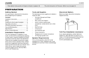
...specialty shops. to read all of less than 4 ohms could damage the unit. UCD200 PREPARATION Getting Started It's a good idea to 7:00 p.m. These kits are needed to install the radio. • Torx type, flathead and Philips screwdrivers • Wire cutters and strippers ...Requirements This unit is designed for power connections • 16-18 gauge speaker wire Speaker Requirements Only connect speakers rated with a load impedance of 4 ohms. Speakers with an existing radio opening. to remove existing radio (screwdriver, socket wrench set or other tools) • Electrical tape &#...
...specialty shops. to read all of less than 4 ohms could damage the unit. UCD200 PREPARATION Getting Started It's a good idea to 7:00 p.m. These kits are needed to install the radio. • Torx type, flathead and Philips screwdrivers • Wire cutters and strippers ...Requirements This unit is designed for power connections • 16-18 gauge speaker wire Speaker Requirements Only connect speakers rated with a load impedance of 4 ohms. Speakers with an existing radio opening. to remove existing radio (screwdriver, socket wrench set or other tools) • Electrical tape &#...
Owners Manual
Page 5
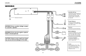
...and amperage. Ground Connect to chassis ground. Never ground negative speaker leads to ground terminal. The red connector is for the right and the white connector is always live. Using an incorrect fuse could damage the radio. If not used, tape bare end of wire. Fuses ...connected. Power Antenna Connect to the radio. WARNING! CAUTION: Failure to wire exactly as shown may cause electrical damage to power antenna or amplifier. Accessory/Ignition Connect to battery or 12 volt power source that is for use with 1 speaker. UCD200 WIRING Antenna Connector WARNING! Never ...
...and amperage. Ground Connect to chassis ground. Never ground negative speaker leads to ground terminal. The red connector is for the right and the white connector is always live. Using an incorrect fuse could damage the radio. If not used, tape bare end of wire. Fuses ...connected. Power Antenna Connect to the radio. WARNING! CAUTION: Failure to wire exactly as shown may cause electrical damage to power antenna or amplifier. Accessory/Ignition Connect to battery or 12 volt power source that is for use with 1 speaker. UCD200 WIRING Antenna Connector WARNING! Never ...
Owners Manual
Page 8
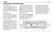
...a maximum of human hearing. "B 00" represents an equal balance level between the rear and front speakers. 5 AM/FM Band Selector (BAND) During radio play, each time the BAND button (5) is pressed, the radio band changes. Press the LOU button (6) to activate this feature will boost the bass and treble ... (4) until "TR" appears on the display panel. Within five seconds, press the AUDIO buttons (3a and 3b) to a maximum of "TR 7". UCD200 OPERATING INSTRUCTIONS 4 Bass Control To adjust the bass level, first select the Bass mode by pressing the SEL button (4) until "BA" appears on the ...
...a maximum of human hearing. "B 00" represents an equal balance level between the rear and front speakers. 5 AM/FM Band Selector (BAND) During radio play, each time the BAND button (5) is pressed, the radio band changes. Press the LOU button (6) to activate this feature will boost the bass and treble ... (4) until "TR" appears on the display panel. Within five seconds, press the AUDIO buttons (3a and 3b) to a maximum of "TR 7". UCD200 OPERATING INSTRUCTIONS 4 Bass Control To adjust the bass level, first select the Bass mode by pressing the SEL button (4) until "BA" appears on the ...


