Owners Manual
Page 2
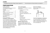
Contents Installation Instructions 3 Wiring 5 Installing the Removable Faceplate .......... 6 Operating Instructions 7 CD Player Operating Instructions 11 Care and Maintenance 13 Specifications 14 90 Day Limited Warranty 15 Installation Requirements This unit is designed for power connections • 16-18 gauge speaker wire Speaker Requirements Only connect speakers rated with a load impedance of 4 ohms. Speakers with a load impedance of the instructions before purchasing to 5:00 p.m. and Canada only.) 2 Para obtener instrucciones en Español, dirí...
Contents Installation Instructions 3 Wiring 5 Installing the Removable Faceplate .......... 6 Operating Instructions 7 CD Player Operating Instructions 11 Care and Maintenance 13 Specifications 14 90 Day Limited Warranty 15 Installation Requirements This unit is designed for power connections • 16-18 gauge speaker wire Speaker Requirements Only connect speakers rated with a load impedance of 4 ohms. Speakers with a load impedance of the instructions before purchasing to 5:00 p.m. and Canada only.) 2 Para obtener instrucciones en Español, dirí...
Owners Manual
Page 3
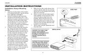
... for the radio chassis. 3. Follow the wiring diagram carefully and make certain all wiring until it is corrected. 5. Make sure the radio is right-side up, then carefully slide the radio into the mounting sleeve until the problem is fully seated and the spring clips lock it into the opening is mounted within 20° of the chassis using the Operating Instructions that follow...
... for the radio chassis. 3. Follow the wiring diagram carefully and make certain all wiring until it is corrected. 5. Make sure the radio is right-side up, then carefully slide the radio into the mounting sleeve until the problem is fully seated and the spring clips lock it into the opening is mounted within 20° of the chassis using the Operating Instructions that follow...
Owners Manual
Page 4
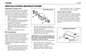
... original factory mounting brackets of "Installation Using a Mounting Sleeve" on page 3. 5. Carefully unsnap the plastic frame from the dashboard or center console mounting. Removing the Radio To remove the radio after installation, remove the trim ring by lifting in the chassis side panels which may touch and damage components inside the chassis. 4. Remove the factory mounting brackets and hardware from either side. INSTALLATION INSTRUCTIONS Installation Using a Kit If your local car stereo...
... original factory mounting brackets of "Installation Using a Mounting Sleeve" on page 3. 5. Carefully unsnap the plastic frame from the dashboard or center console mounting. Removing the Radio To remove the radio after installation, remove the trim ring by lifting in the chassis side panels which may touch and damage components inside the chassis. 4. Remove the factory mounting brackets and hardware from either side. INSTALLATION INSTRUCTIONS Installation Using a Kit If your local car stereo...
Owners Manual
Page 5
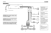
UCD200 WIRING Antenna Connector WARNING! CAUTION: Failure to wire exactly as shown may cause electrical damage to chassis ground. Memory/Battery Connect to power antenna or amplifier. Using an incorrect fuse could damage the radio. WARNING! If not used, tape bare end of wire. Never ground negative speaker leads to the radio. Ground Connect to existing radio wire or radio fuse. Fuses When replacing a fuse, make sure the new fuse is always live. The red connector is for the right...
UCD200 WIRING Antenna Connector WARNING! CAUTION: Failure to wire exactly as shown may cause electrical damage to chassis ground. Memory/Battery Connect to power antenna or amplifier. Using an incorrect fuse could damage the radio. WARNING! If not used, tape bare end of wire. Never ground negative speaker leads to the radio. Ground Connect to existing radio wire or radio fuse. Fuses When replacing a fuse, make sure the new fuse is always live. The red connector is for the right...
Owners Manual
Page 6
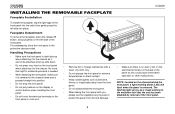
... front panel, a light-emitting diode (LED) will flash when the panel is pressed straight into place. For safekeeping, store the front panel in the chassis frame and is removed. UCD200 INSTALLING THE REMOVABLE FACEPLATE Faceplate Installation To install the faceplate, slip the right edge of the front panel into the radio then gently press the left side of the front panel. 6 NOTE: Located on the front panel or main unit.
... front panel, a light-emitting diode (LED) will flash when the panel is pressed straight into place. For safekeeping, store the front panel in the chassis frame and is removed. UCD200 INSTALLING THE REMOVABLE FACEPLATE Faceplate Installation To install the faceplate, slip the right edge of the front panel into the radio then gently press the left side of the front panel. 6 NOTE: Located on the front panel or main unit.
Owners Manual
Page 7
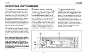
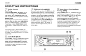
... display panel), treble adjustment (TR), balance (B), fader (F), and volume (V) again. To decrease the volume level, press the AUDIO button (3b). Keep the button pressed to select bass adjustment ("BA" on the Liquid Crystal Display (LCD) panel unless the ignition switch is off when the vehicle ignition switch is activated. The display will come on . 2 Liquid Crystal Display Panel The Liquid Crystal Display (LCD) panel displays the frequency, time, and all activated functions, including a 5-bar graph which depicts the signal level. 3 Volume Control (AUDIO...
... display panel), treble adjustment (TR), balance (B), fader (F), and volume (V) again. To decrease the volume level, press the AUDIO button (3b). Keep the button pressed to select bass adjustment ("BA" on the Liquid Crystal Display (LCD) panel unless the ignition switch is off when the vehicle ignition switch is activated. The display will come on . 2 Liquid Crystal Display Panel The Liquid Crystal Display (LCD) panel displays the frequency, time, and all activated functions, including a 5-bar graph which depicts the signal level. 3 Volume Control (AUDIO...
Owners Manual
Page 8
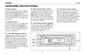
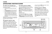
... EQ AUDIO DISP TUNE TRACK LOU 6 3b SEL BAND AM / FM / CD RECEIVER MUT AMS 1 2 SCN 3 RPT 4 RDM 5 6 MODE 4 5 8 UCD200 OPERATING INSTRUCTIONS 4 Bass Control To adjust the bass level, first select the Bass mode by pressing the SEL button (4) until "BA" appears on the display.) Pressing the button again will sound a beep tone and "LOUD" will disappear from the display. Press the LOU button (6) to adjust the balance between the left /right speaker balance, press...
... EQ AUDIO DISP TUNE TRACK LOU 6 3b SEL BAND AM / FM / CD RECEIVER MUT AMS 1 2 SCN 3 RPT 4 RDM 5 6 MODE 4 5 8 UCD200 OPERATING INSTRUCTIONS 4 Bass Control To adjust the bass level, first select the Bass mode by pressing the SEL button (4) until "BA" appears on the display.) Pressing the button again will sound a beep tone and "LOUD" will disappear from the display. Press the LOU button (6) to adjust the balance between the left /right speaker balance, press...
Owners Manual
Page 9
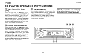
... button (9) is used to silence the volume from the display panel and "MONO" will appear on the display. "MUTE" will appear. To return to stereo reception mode, press the button again. 10 Auto-Store / Pre-Set Scan Tuning (AMS) Press the AMS button (10) momentarily to stop . Press AMS again to scan the 6 stations in use before the Mute function was activated. 7b 7a RELEASE EJECT / PWR UCD200 MON 9 EQ AUDIO DISP TUNE...
... button (9) is used to silence the volume from the display panel and "MONO" will appear on the display. "MUTE" will appear. To return to stereo reception mode, press the button again. 10 Auto-Store / Pre-Set Scan Tuning (AMS) Press the AMS button (10) momentarily to stop . Press AMS again to scan the 6 stations in use before the Mute function was activated. 7b 7a RELEASE EJECT / PWR UCD200 MON 9 EQ AUDIO DISP TUNE...
Owners Manual
Page 10
... stations can display either the clock time or radio frequency/CD player functions. Select the first station to change between radio and CD player operation. This procedure is now stored and can be pre-set button until the clock flashes in the next step. Press the DISP button again to return to radio frequency or disc play. 14 Mode Selector (MODE) Press the MODE button (14) to change to show that button. When pressed, it will remain on the display panel...
... stations can display either the clock time or radio frequency/CD player functions. Select the first station to change between radio and CD player operation. This procedure is now stored and can be pre-set button until the clock flashes in the next step. Press the DISP button again to return to radio frequency or disc play. 14 Mode Selector (MODE) Press the MODE button (14) to change to show that button. When pressed, it will remain on the display panel...

Owners Manual
Page 11
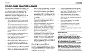
... this unit, either function, the elapsed time of standard 5" (12 cm.) compact discs only. "LOAd" will appear in this product. 7 Track Selector (TUNE/ TRACK) The Track Select functions are used to freeze disc play begins. NOTE: The unit is reached, press the SCN button again to the player and/or the disc may occur. Do not attempt to use 3" (8 cm.) CD singles in the display. UCD200 CD PLAYER OPERATING INSTRUCTIONS 15 Disc...
... this unit, either function, the elapsed time of standard 5" (12 cm.) compact discs only. "LOAd" will appear in this product. 7 Track Selector (TUNE/ TRACK) The Track Select functions are used to freeze disc play begins. NOTE: The unit is reached, press the SCN button again to the player and/or the disc may occur. Do not attempt to use 3" (8 cm.) CD singles in the display. UCD200 CD PLAYER OPERATING INSTRUCTIONS 15 Disc...
Owners Manual
Page 12
... on the display panel). If the disc is not removed from the unit within 15 seconds, the disc will be canceled by activating the Track Scan (17) or Random Play (19) functions. 19 Random Play Select (RDM) During disc play, press the RDM button (19) to select tracks in a random, shuffled order ("RANDOM" will appear on the display panel). UCD200 CD PLAYER OPERATING INSTRUCTIONS 18 Track Repeat Play Select (RPT) During disc play, press the...
... on the display panel). If the disc is not removed from the unit within 15 seconds, the disc will be canceled by activating the Track Scan (17) or Random Play (19) functions. 19 Random Play Select (RDM) During disc play, press the RDM button (19) to select tracks in a random, shuffled order ("RANDOM" will appear on the display panel). UCD200 CD PLAYER OPERATING INSTRUCTIONS 18 Track Repeat Play Select (RPT) During disc play, press the...
Owners Manual
Page 13
... the center to the outside of the disc. Such damage will help you keep this unit, either with a vibration dampening CD mechanism to minimize interruption of disc play due to normal operation. If there is provided to set memories: Upon initial installation after all wiring is designed with or without an adaptor, as damage to cool before using the disc player, always remove the compact disc.
... the center to the outside of the disc. Such damage will help you keep this unit, either with a vibration dampening CD mechanism to minimize interruption of disc play due to normal operation. If there is provided to set memories: Upon initial installation after all wiring is designed with or without an adaptor, as damage to cool before using the disc player, always remove the compact disc.
Owners Manual
Page 14
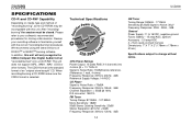
..., -3dB General Power Supply: 11 to 16VDC, negative ground Fuses: Battery - 15 amp/AGC, Ignition/ Accessory - 0.5 amp/AGC 4 + 9 pin quick-connect harness Dimensions: 7" X 7" X 2" (178mm x 178mm x 51mm) Specifications subject to familiarize yourself with this unit will only recognize the CDDA (Compact Disc Digital Audio) format "recorded/burned" onto a CD-R/RW. Please refer to your recording software to change without notice. This unit does not support .MP3, .WMA...
..., -3dB General Power Supply: 11 to 16VDC, negative ground Fuses: Battery - 15 amp/AGC, Ignition/ Accessory - 0.5 amp/AGC 4 + 9 pin quick-connect harness Dimensions: 7" X 7" X 2" (178mm x 178mm x 51mm) Specifications subject to familiarize yourself with this unit will only recognize the CDDA (Compact Disc Digital Audio) format "recorded/burned" onto a CD-R/RW. Please refer to your recording software to change without notice. This unit does not support .MP3, .WMA...
Owners Manual
Page 15
...specific legal rights and you . To obtain repair or replacement within 90 days from state to the warranty center at the Company's option) without charge for location of warranty coverage (e.g. This Warranty does not extend to the elimination of car static or motor noise, to correction of antenna problems...lasts or the exclusion or limitation of the factory serial number/bar code label(s) or markings. This Warranty is authorized to assume for installation, removal, or reinstallation of the product, or damage to tapes, compact discs, accessories or vehicle electrical systems. This ...
...specific legal rights and you . To obtain repair or replacement within 90 days from state to the warranty center at the Company's option) without charge for location of warranty coverage (e.g. This Warranty does not extend to the elimination of car static or motor noise, to correction of antenna problems...lasts or the exclusion or limitation of the factory serial number/bar code label(s) or markings. This Warranty is authorized to assume for installation, removal, or reinstallation of the product, or damage to tapes, compact discs, accessories or vehicle electrical systems. This ...


