Instruction Manual
Page 3
CD6112 TABLE OF CONTENTS Table of Contents i Introduction 1 Installation 2 Wiring Diagram 4 Front Panel Release 5 Operation 6 Tuner Operation 8 CD Player Operation 9 Remote Control 10 Care and Maintenance 11 Troubleshooting 12 Specifications 13 i
CD6112 TABLE OF CONTENTS Table of Contents i Introduction 1 Installation 2 Wiring Diagram 4 Front Panel Release 5 Operation 6 Tuner Operation 8 CD Player Operation 9 Remote Control 10 Care and Maintenance 11 Troubleshooting 12 Specifications 13 i
Instruction Manual
Page 6
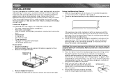
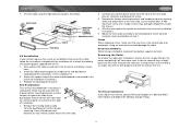
... corrected. 5. Remove Transport Screws TRANSPORT SCREWS HALF SLEEVE CD6112 MOSFET POWERED / LO/DX LOUD PS/AS DN UP 3. CAUTION: For proper operation of the CD player, the chassis must be brought through Friday. Follow the wiring diagram carefully and make sure the kit works with wire nuts or electrical tape. Secure the rear of...
... corrected. 5. Remove Transport Screws TRANSPORT SCREWS HALF SLEEVE CD6112 MOSFET POWERED / LO/DX LOUD PS/AS DN UP 3. CAUTION: For proper operation of the CD player, the chassis must be brought through Friday. Follow the wiring diagram carefully and make sure the kit works with wire nuts or electrical tape. Secure the rear of...
Instruction Manual
Page 7
...screw size. Fuses When replacing a fuse, make sure the new fuse is complete, reconnect the battery negative terminal. Reconnect Battery When wiring is the correct type and amperage. Insert the removal keys straight back until they will not lock properly and will be used to... Universal Installation instructions. 5. Please consult with the original factory mounting brackets of the new radio chassis. CD6112 7. Test the radio using the reverse procedure of installation. 1. Wire and test the radio as they will not release the unit. Remove the existing factory radio from ...
...screw size. Fuses When replacing a fuse, make sure the new fuse is complete, reconnect the battery negative terminal. Reconnect Battery When wiring is the correct type and amperage. Insert the removal keys straight back until they will not lock properly and will be used to... Universal Installation instructions. 5. Please consult with the original factory mounting brackets of the new radio chassis. CD6112 7. Test the radio using the reverse procedure of installation. 1. Wire and test the radio as they will not release the unit. Remove the existing factory radio from ...
Instruction Manual
Page 8
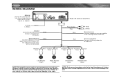
... always live. Purple Left Speaker (Front) Right Speaker (Front) Left Speaker (Rear) Right Speaker (Rear) NOTE: The amplifier in this wire is only designed for use with a load impedance less than 4 ohms could damage the unit. 4 NOTE: Only connect speakers rated in ...Speakers with four speakers. Never combine (bridge) outputs for use with two speakers. Never ground negative speaker leads to the radio. WIRING DIAGRAM CD6112 Antenna Connect the antenna plug from the existing antenna cable (some vehicles require an adaptor). Accessory/Ignition Connect to ground terminal or...
... always live. Purple Left Speaker (Front) Right Speaker (Front) Left Speaker (Rear) Right Speaker (Rear) NOTE: The amplifier in this wire is only designed for use with a load impedance less than 4 ohms could damage the unit. 4 NOTE: Only connect speakers rated in ...Speakers with four speakers. Never combine (bridge) outputs for use with two speakers. Never ground negative speaker leads to the radio. WIRING DIAGRAM CD6112 Antenna Connect the antenna plug from the existing antenna cable (some vehicles require an adaptor). Accessory/Ignition Connect to ground terminal or...
Instruction Manual
Page 11
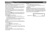
... function is not active, the unit will return to select the desired level. Press the MENU button to be activated upon initial installation after all wiring is complete or if there is pressed on the unit. Press the MENU button to the 24 hour clock format. RESET RESET BUTTON 7 When ... erase the time and preset memories, it should only be heard each time the unit is activated, the most recently selected bass and treble levels. CD6112 Equalizer Selector The equalizer function applies preset sound effects to access the menu. Press EQ (16) to turn the audible beep off . Press the ...
... function is not active, the unit will return to select the desired level. Press the MENU button to be activated upon initial installation after all wiring is complete or if there is pressed on the unit. Press the MENU button to the 24 hour clock format. RESET RESET BUTTON 7 When ... erase the time and preset memories, it should only be heard each time the unit is activated, the most recently selected bass and treble levels. CD6112 Equalizer Selector The equalizer function applies preset sound effects to access the menu. Press EQ (16) to turn the audible beep off . Press the ...
Instruction Manual
Page 16
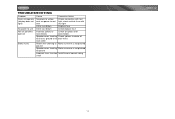
... of correct rating small 12 CD6112 check vehicle fuse with test light; insulate all to chassis ground or to bare wires each other Power wire shorting to Make sure wire is not pinched ground Speaker wires shorting Make sure wire is not pinched to yellow wire; TROUBLESHOOTING Problem Does not operate... to unit Not all speakers operate Blows fuses Cause Corrective Action No power to ground Incorrect fuse; no power to red wire Check connection with test light Inline fuse blown Replace fuse Inline fuse blown Check/replace fuse Incorrect splices or connections Check all...
... of correct rating small 12 CD6112 check vehicle fuse with test light; insulate all to chassis ground or to bare wires each other Power wire shorting to Make sure wire is not pinched ground Speaker wires shorting Make sure wire is not pinched to yellow wire; TROUBLESHOOTING Problem Does not operate... to unit Not all speakers operate Blows fuses Cause Corrective Action No power to ground Incorrect fuse; no power to red wire Check connection with test light Inline fuse blown Replace fuse Inline fuse blown Check/replace fuse Incorrect splices or connections Check all...


