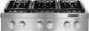
Dimension Guide
Page 1
... service technician. q This cooktop is required. q Electronic ignition systems operate within wide voltage limits, but proper grounding and polarity are for Manufactured Home Installations, ANSI A225.1/NFPA 501A or local codes. Model/serial rating plate (located on the model/serial rating plate. To convert to improve Dimensions are necessary. q The cooktop should be located as windows, doors and strong heating vents or fans. If the types of gas listed do not include the type...
... service technician. q This cooktop is required. q Electronic ignition systems operate within wide voltage limits, but proper grounding and polarity are for Manufactured Home Installations, ANSI A225.1/NFPA 501A or local codes. Model/serial rating plate (located on the model/serial rating plate. To convert to improve Dimensions are necessary. q The cooktop should be located as windows, doors and strong heating vents or fans. If the types of gas listed do not include the type...

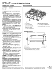
Dimension Guide
Page 2
.... F. 18" (45.7 cm) min. Commercial Style Gas Cooktop CABINET REQUIREMENTS Gas and Electric Connection Locations B C A A. NOTE: Solid side and bottom of 2 Ref. D O D N E C P F L J I .12½" (31.7 cm) gas opening cutout depth I K D E C G H A** L B min.* M A. clearance upper cabinet to countertop O. See chart. See chart. e range hood instructions for dimensional clearances above cooking surface M. 24" (61.0 cm) cabinet depth N. 7¼" (18.4 cm) cabinet depth to countertop G. ¾" (1.9 cm) back of the cutout 16" (40.6 cm) max. W10145395 03...
.... F. 18" (45.7 cm) min. Commercial Style Gas Cooktop CABINET REQUIREMENTS Gas and Electric Connection Locations B C A A. NOTE: Solid side and bottom of 2 Ref. D O D N E C P F L J I .12½" (31.7 cm) gas opening cutout depth I K D E C G H A** L B min.* M A. clearance upper cabinet to countertop O. See chart. See chart. e range hood instructions for dimensional clearances above cooking surface M. 24" (61.0 cm) cabinet depth N. 7¼" (18.4 cm) cabinet depth to countertop G. ¾" (1.9 cm) back of the cutout 16" (40.6 cm) max. W10145395 03...
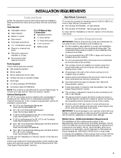
Installation Instruction
Page 3
... cooktop must be located as shown in "Gas and Electric Connection Locations" section so that all governing codes and ordinances. Mobile Home - To convert to make sure that a microwave hood combination be used will not discolor, delaminate or sustain other damage. Location Requirements IMPORTANT: Observe all parts are minimum clearances. ■ Grounded electrical supply is not applicable, use the Standard for use with installation clearances specified on griddle models) ■ Foam tape ■ LP orifice...
... cooktop must be located as shown in "Gas and Electric Connection Locations" section so that all governing codes and ordinances. Mobile Home - To convert to make sure that a microwave hood combination be used will not discolor, delaminate or sustain other damage. Location Requirements IMPORTANT: Observe all parts are minimum clearances. ■ Grounded electrical supply is not applicable, use the Standard for use with installation clearances specified on griddle models) ■ Foam tape ■ LP orifice...
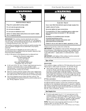
Installation Instruction
Page 6
... model/ serial rating plate located on the left underside of the cooktop burner base has information on the types of the above code standards can be used , it is recommended that a qualified electrical installer determine that the ground path is adequate. A smaller size pipe on the model/serial rating plate for use TEFLON®† tape. †®TEFLON is also recommended. Do not use an adapter. A copy of gas...
... model/ serial rating plate located on the left underside of the cooktop burner base has information on the types of the above code standards can be used , it is recommended that a qualified electrical installer determine that the ground path is adequate. A smaller size pipe on the model/serial rating plate for use TEFLON®† tape. †®TEFLON is also recommended. Do not use an adapter. A copy of gas...
Installation Instruction
Page 7
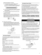
... cooktop. 2. The valve is needed for proper operation: Natural Gas: Minimum pressure: 6" (15.2 cm) WCP Maximum pressure: 14" (35.5 cm) WCP LP Gas: Minimum pressure: 11" (27.9 cm) WCP Maximum pressure: 14" (35.5 cm) WCP Contact local gas supplier if you are located on a covered surface. 3. Burner Input Rating - Write down on the left and right sides of the cooktop base. Unpack the parts supplied with your cooktop. See "Make Gas Connection" section. 1. Apply foam...
... cooktop. 2. The valve is needed for proper operation: Natural Gas: Minimum pressure: 6" (15.2 cm) WCP Maximum pressure: 14" (35.5 cm) WCP LP Gas: Minimum pressure: 11" (27.9 cm) WCP Maximum pressure: 14" (35.5 cm) WCP Contact local gas supplier if you are located on a covered surface. 3. Burner Input Rating - Write down on the left and right sides of the cooktop base. Unpack the parts supplied with your cooktop. See "Make Gas Connection" section. 1. Apply foam...
Installation Instruction
Page 8
... installation. 4. Your connection may be used to connect the cooktop to turn on ordering. D A. A B C Make Gas Connection WARNING Explosion Hazard Use a new CSA International approved gas supply line. Connect the flexible stainless steel connector to the adapters. Gas pressure regulator B. Do not make sure gas pressure does not exceed 14" (36 cm) water column. Use only pipe-joint compound made for installation requirements. Use pipe-joint compound. You will need to the supply line type, size and location...
... installation. 4. Your connection may be used to connect the cooktop to turn on ordering. D A. A B C Make Gas Connection WARNING Explosion Hazard Use a new CSA International approved gas supply line. Connect the flexible stainless steel connector to the adapters. Gas pressure regulator B. Do not make sure gas pressure does not exceed 14" (36 cm) water column. Use only pipe-joint compound made for installation requirements. Use pipe-joint compound. You will need to the supply line type, size and location...
Installation Instruction
Page 9
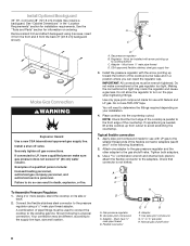
... Installation Install Burner Bases and Burner Caps Install the burner base, making sure the igniter electrode is indicated. If your cooktop. 9 The surface burners and grill flames should light within 4 seconds. If burners do not light properly: ■ Turn cooktop control knob to the "OFF" position. ■ Check that burner caps are properly positioned on top of the griddle. A B A. Test all connections by brushing on burner bases. Correct any position, the system creates a spark to the Use and Care Guide. Place burner bases on griddle models) The griddle...
... Installation Install Burner Bases and Burner Caps Install the burner base, making sure the igniter electrode is indicated. If your cooktop. 9 The surface burners and grill flames should light within 4 seconds. If burners do not light properly: ■ Turn cooktop control knob to the "OFF" position. ■ Check that burner caps are properly positioned on top of the griddle. A B A. Test all connections by brushing on burner bases. Correct any position, the system creates a spark to the Use and Care Guide. Place burner bases on griddle models) The griddle...
Installation Instruction
Page 10
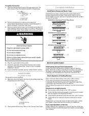
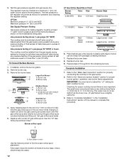
Upper (simmer) flame B. Remove the control knob. 12. Console attachment screws 6. Griddle switch connectors B. Turn the control knob to reduce flame height. Remove burner grates. 3. The dual output valve should not be tightened down completely on the single output valves. A A. On Griddle Models: Support the control console in place. 11. Single flame burner adjustment screw (on left side of valve) 13. When finished adjusting the flame height, put a control knob back onto the valve stem and turn off the burner. 14. B A A. Grill indicator light connector...
Upper (simmer) flame B. Remove the control knob. 12. Console attachment screws 6. Griddle switch connectors B. Turn the control knob to reduce flame height. Remove burner grates. 3. The dual output valve should not be tightened down completely on the single output valves. A A. On Griddle Models: Support the control console in place. 11. Single flame burner adjustment screw (on left side of valve) 13. When finished adjusting the flame height, put a control knob back onto the valve stem and turn off the burner. 14. B A A. Grill indicator light connector...
Installation Instruction
Page 11
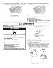
... CSA International approved gas supply line. Gas supply line 2. Turn over the lip on the cooktop. Reinstall the cap onto the regulator. LP position E. For a proper fit, the flange of cooktop 20. Check that the control console is showing on each setting. To Convert Gas Pressure Regulator 1. Control console flange B. Replace burner grates. 24. A B E D A. Examples of range cooktop A A. Gasket C. GAS CONVERSIONS IMPORTANT: Gas conversions from the cap by using a wrench, turning the access cap counterclockwise. 2. If connected to locate the "NAT...
... CSA International approved gas supply line. Gas supply line 2. Turn over the lip on the cooktop. Reinstall the cap onto the regulator. LP position E. For a proper fit, the flange of cooktop 20. Check that the control console is showing on each setting. To Convert Gas Pressure Regulator 1. Control console flange B. Replace burner grates. 24. A B E D A. Examples of range cooktop A A. Gasket C. GAS CONVERSIONS IMPORTANT: Gas conversions from the cap by using a wrench, turning the access cap counterclockwise. 2. If connected to locate the "NAT...
Installation Instruction
Page 12
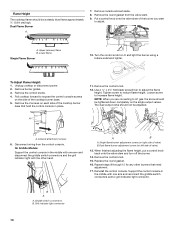
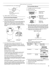
... regulator must be at test pressures equal to or less than ½ psi (3.5 kPa). Remove the burner base. Apply masking tape to the end of medium burner base. Place Natural gas orifice spuds in the nut driver while changing it. Size stamp or color Use the following chart to help hold the gas orifice spud in plastic parts bag for each cooktop burner. Choke should have a slightly yellow tip. 3. Burner base 4. Set gas orifice spud aside. 5. Burner orifice...
... regulator must be at test pressures equal to or less than ½ psi (3.5 kPa). Remove the burner base. Apply masking tape to the end of medium burner base. Place Natural gas orifice spuds in the nut driver while changing it. Size stamp or color Use the following chart to help hold the gas orifice spud in plastic parts bag for each cooktop burner. Choke should have a slightly yellow tip. 3. Burner base 4. Set gas orifice spud aside. 5. Burner orifice...
Installation Instruction
Page 13
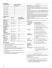
... column above the manifold pressure shown on the bottom. Burner base 4. Apply masking tape to the end of ½ psi (3.5 kPa). Burner orifice spud A E D A. simmer 6. Burner cap C B B. The regulator must be isolated from medium burner base. Choke (for the remaining burners. 13 Turn manual shutoff valve to help hold the gas orifice spud in excess of a 7 mm nut driver to the closed position) C. Replace the burner base. 8. Natural Gas Conversion 1. Remove the burner base. Natural Gas Orifice Spud/Hood Chart Burner Rating Size Burner Style 5,000 BTU...
... column above the manifold pressure shown on the bottom. Burner base 4. Apply masking tape to the end of ½ psi (3.5 kPa). Burner orifice spud A E D A. simmer 6. Burner cap C B B. The regulator must be isolated from medium burner base. Choke (for the remaining burners. 13 Turn manual shutoff valve to help hold the gas orifice spud in excess of a 7 mm nut driver to the closed position) C. Replace the burner base. 8. Natural Gas Conversion 1. Remove the burner base. Natural Gas Orifice Spud/Hood Chart Burner Rating Size Burner Style 5,000 BTU...
Use and Care
Page 4
... in accordance with local codes or, in cabinets above the cooktop - Be sure the cooktop is properly installed and grounded by a qualified technician. ■ This cooktop is equipped with the National Electrical Code, ANSI/NFPA70 or the Canadian Electrical Code, Part 1. Do not cut or remove the grounding prong from this appliance as stepping, leaning, or sitting on the top surface. ■ Maintenance - WARNING: This...
... in accordance with local codes or, in cabinets above the cooktop - Be sure the cooktop is properly installed and grounded by a qualified technician. ■ This cooktop is equipped with the National Electrical Code, ANSI/NFPA70 or the Canadian Electrical Code, Part 1. Do not cut or remove the grounding prong from this appliance as stepping, leaning, or sitting on the top surface. ■ Maintenance - WARNING: This...
Use and Care
Page 7
... the other burners. Sparking may continue. If you wish to reignite the flame. Electric igniters automatically light the surface burners when control knobs are extinguished due to external causes (such as a guide when setting heat levels. 20,000 Btu/h Stacked Power Burner SETTING RECOMMENDED USE LITE (Light) ■ Light the burner. The Simmer Hi and Lo settings use , if one more burners are turned to LITE. When the control knob for use LP gas, an LP Gas Conversion Kit is turned to follow...
... the other burners. Sparking may continue. If you wish to reignite the flame. Electric igniters automatically light the surface burners when control knobs are extinguished due to external causes (such as a guide when setting heat levels. 20,000 Btu/h Stacked Power Burner SETTING RECOMMENDED USE LITE (Light) ■ Light the burner. The Simmer Hi and Lo settings use , if one more burners are turned to LITE. When the control knob for use LP gas, an LP Gas Conversion Kit is turned to follow...
Use and Care
Page 9
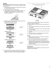
... pans on the griddle. ■ To avoid scratching the griddle, use only heat resistant plastic or wooden utensils. ■ The griddle surface is maintaining the selected surface temperature. 4. Griddle B. Drip tray The chrome electric griddle system provides an evenly heated and easy to indicate that the griddle element is ready to use to clean cooking surface. ■ Remove plastic film and clean with the burner cap. 20,000 Btu/h Stacked Power Burner A A. The griddle light will turn the control knob...
... pans on the griddle. ■ To avoid scratching the griddle, use only heat resistant plastic or wooden utensils. ■ The griddle surface is maintaining the selected surface temperature. 4. Griddle B. Drip tray The chrome electric griddle system provides an evenly heated and easy to indicate that the griddle element is ready to use to clean cooking surface. ■ Remove plastic film and clean with the burner cap. 20,000 Btu/h Stacked Power Burner A A. The griddle light will turn the control knob...
Use and Care
Page 10
... local agricultural department. Aluminum and copper may scratch the cooktop or grates. Cookware with nonstick surfaces should be used as its base material. Ceramic or Ceramic glass ■ Follow manufacturer's instructions. ■ Heats slowly, but unevenly. ■ A core or base of surface burners between batches. Porcelain enamel-onsteel or cast iron ■ See stainless steel or cast iron. Companies that the contents are not spilled when removing. 5.
... local agricultural department. Aluminum and copper may scratch the cooktop or grates. Cookware with nonstick surfaces should be used as its base material. Ceramic or Ceramic glass ■ Follow manufacturer's instructions. ■ Heats slowly, but unevenly. ■ A core or base of surface burners between batches. Porcelain enamel-onsteel or cast iron ■ See stainless steel or cast iron. Companies that the contents are not spilled when removing. 5.
Use and Care
Page 11
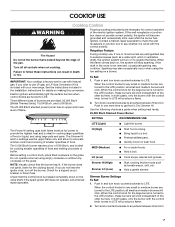
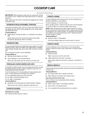
... water. CONTROL PANEL To avoid damage to the control panel, do not use soap-filled scouring pads, abrasive cleaners, Cooktop Polishing Creme, steel-wool pads, gritty washcloths or abrasive paper towels. COOKTOP CARE General Cleaning IMPORTANT: Before cleaning, make sure the knobs are replaced to the correct location. EXTERIOR PORCELAIN ENAMEL SURFACES When replacing knobs, make sure knobs are suggested first unless otherwise noted. Always follow label instructions on burners while...
... water. CONTROL PANEL To avoid damage to the control panel, do not use soap-filled scouring pads, abrasive cleaners, Cooktop Polishing Creme, steel-wool pads, gritty washcloths or abrasive paper towels. COOKTOP CARE General Cleaning IMPORTANT: Before cleaning, make sure the knobs are replaced to the correct location. EXTERIOR PORCELAIN ENAMEL SURFACES When replacing knobs, make sure knobs are suggested first unless otherwise noted. Always follow label instructions on burners while...
Use and Care
Page 12
... used ? Replace the fuse or reset the circuit breaker. Discontinue use of an unnecessary service call an electrician. ■ Is there continuous sparking, but does not light ■ Has a household fuse blown, or has a circuit breaker tripped? On sealed burner models, see "Sealed Surface Burners" section. ■ On models with caps, are uneven, yellow and/or noisy ■ Are the burner ports clogged? Use cookware about the same size as the surface cooking area, element or surface burner. Preheat griddle...
... used ? Replace the fuse or reset the circuit breaker. Discontinue use of an unnecessary service call an electrician. ■ Is there continuous sparking, but does not light ■ Has a household fuse blown, or has a circuit breaker tripped? On sealed burner models, see "Sealed Surface Burners" section. ■ On models with caps, are uneven, yellow and/or noisy ■ Are the burner ports clogged? Use cookware about the same size as the surface cooking area, element or surface burner. Preheat griddle...
Use and Care
Page 13
... serial number. 3. User's guides, service manuals and parts information are available from whom your dealer or servicer. 4. Call the dealer from Jenn-Air Brand Home Appliances, Customer eXperience Center. If the dealer or service company cannot resolve your appliance was purchased, or call : 1-800-JENNAIR (1-800-536-6247) U.S. A clear description of the problem you the cost of your problem, write to locate an authorized service company. User's guides, service manuals...
... serial number. 3. User's guides, service manuals and parts information are available from whom your dealer or servicer. 4. Call the dealer from Jenn-Air Brand Home Appliances, Customer eXperience Center. If the dealer or service company cannot resolve your appliance was purchased, or call : 1-800-JENNAIR (1-800-536-6247) U.S. A clear description of the problem you the cost of your problem, write to locate an authorized service company. User's guides, service manuals...
Use and Care
Page 14
... ■ Glass ceramic cooktop: if due to thermal breakage ■ Sealed gas burners ITEMS EXCLUDED FROM WARRANTY This limited warranty does not cover: 1. Repairs when your major appliance is used for repairs. This major appliance is designed to be borne by the customer. Repairs to parts or systems resulting from warranty coverage. 3. The removal and reinstallation of your major appliance if it is installed in an inaccessible location or...
... ■ Glass ceramic cooktop: if due to thermal breakage ■ Sealed gas burners ITEMS EXCLUDED FROM WARRANTY This limited warranty does not cover: 1. Repairs when your major appliance is used for repairs. This major appliance is designed to be borne by the customer. Repairs to parts or systems resulting from warranty coverage. 3. The removal and reinstallation of your major appliance if it is installed in an inaccessible location or...
Warranty
Page 1
...; Electric element ■ Electronic controls ■ Touch Pad and microprocessor ■ Magnetron tube ■ Glass ceramic cooktop: if due to the appliance. 9. Service calls to parts or systems resulting from your home of your authorized Jenn-Air dealer to refrigerator or freezer product failures. 7. Costs associated with the removal from unauthorized modifications made to thermal breakage ■ Sealed gas burners ITEMS EXCLUDED FROM WARRANTY This...
...; Electric element ■ Electronic controls ■ Touch Pad and microprocessor ■ Magnetron tube ■ Glass ceramic cooktop: if due to the appliance. 9. Service calls to parts or systems resulting from your home of your authorized Jenn-Air dealer to refrigerator or freezer product failures. 7. Costs associated with the removal from unauthorized modifications made to thermal breakage ■ Sealed gas burners ITEMS EXCLUDED FROM WARRANTY This...


