
Instruction Manual
Page 2
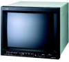
ENGLISH INSTRUCTIONS COLOR VIDEO MONITOR TM-H150CG Thank you for purchasing this JVC color video monitor. Before using it, read and follow all instructions carefully to take full advantage of the monitor's capabilities.
ENGLISH INSTRUCTIONS COLOR VIDEO MONITOR TM-H150CG Thank you for purchasing this JVC color video monitor. Before using it, read and follow all instructions carefully to take full advantage of the monitor's capabilities.
Instruction Manual
Page 3
.... Reorient or relocate the receiving antenna. - Disposal of the cabinet. in dusty places, - if the unit has been dropped or the cabinet has been damaged, - Use of manufacture's specified replacement parts... will tread on the cord. only) This product utilizes both a Cathode Ray Tube (CRT) and other components that the replacement parts he/ she uses have the service personnel verify... disposal could result in a picture tube implosion. This monitor is damaged, - only) CAUTION: Changes or modification not approved by JVC could void the user's authority to dangerous voltage or...
.... Reorient or relocate the receiving antenna. - Disposal of the cabinet. in dusty places, - if the unit has been dropped or the cabinet has been damaged, - Use of manufacture's specified replacement parts... will tread on the cord. only) This product utilizes both a Cathode Ray Tube (CRT) and other components that the replacement parts he/ she uses have the service personnel verify... disposal could result in a picture tube implosion. This monitor is damaged, - only) CAUTION: Changes or modification not approved by JVC could void the user's authority to dangerous voltage or...
Instruction Manual
Page 4
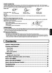
...PRECAUTIONS 2 Controls and Features 4 Front Panel ...4 Rear Panel ...6 Input Card (option 7 Preparation ...9 Installing the Input Card 9 Basic Menu Operations (MENU, SET-UP MENU 10 How to.... Please follow the procedures below. * For stable operation of the CRT, approximately 30 minutes running time is required from outside using a degausser... Power Cord for AC 120 V as for monitor operation = This monitor uses a high precision CRT (cathode ray tube). When it can generate ...the time the power is turned on. * When the monitor is not recommended to keep a certain still image displayed on...
...PRECAUTIONS 2 Controls and Features 4 Front Panel ...4 Rear Panel ...6 Input Card (option 7 Preparation ...9 Installing the Input Card 9 Basic Menu Operations (MENU, SET-UP MENU 10 How to.... Please follow the procedures below. * For stable operation of the CRT, approximately 30 minutes running time is required from outside using a degausser... Power Cord for AC 120 V as for monitor operation = This monitor uses a high precision CRT (cathode ray tube). When it can generate ...the time the power is turned on. * When the monitor is not recommended to keep a certain still image displayed on...
Instruction Manual
Page 6
... properly. • PHASE should be checked only when the NTSC signal is not available to the VIDEO B terminal, the Y/C signal has priority over the composite signal. p Power lamp Unlit: The main power is off the monitor when the main power is adjusted properly. • For ...or the Y/C (S-video) signal is 16:9. • Pressing the button again returns the aspect ratio to 4:3. 9 INPUT SELECT buttons Select an input to the input card installed in stand- C/D (SLOT): Select the signal input to display. q Stand-by button is pressed and when the monitor actually turns on the screen. 8 ...
... properly. • PHASE should be checked only when the NTSC signal is not available to the VIDEO B terminal, the Y/C signal has priority over the composite signal. p Power lamp Unlit: The main power is off the monitor when the main power is adjusted properly. • For ...or the Y/C (S-video) signal is 16:9. • Pressing the button again returns the aspect ratio to 4:3. 9 INPUT SELECT buttons Select an input to the input card installed in stand- C/D (SLOT): Select the signal input to display. q Stand-by button is pressed and when the monitor actually turns on the screen. 8 ...
Instruction Manual
Page 7
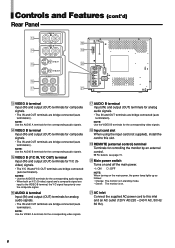
... outlet (120 V AC/220 - 240 V AC, 50 Hz/ 60 Hz). 6 NOTE: Use the VIDEO A terminals for controlling the monitor by mode. • Green: The monitor is on. i Input card slot When using the input card (not supplied), install the card to this slot. o REMOTE (external control) terminal Terminals for the corresponding video signals. t VIDEO B (Y/C IN,Y/C OUT) terminal...
... outlet (120 V AC/220 - 240 V AC, 50 Hz/ 60 Hz). 6 NOTE: Use the VIDEO A terminals for controlling the monitor by mode. • Green: The monitor is on. i Input card slot When using the input card (not supplied), install the card to this slot. o REMOTE (external control) terminal Terminals for the corresponding video signals. t VIDEO B (Y/C IN,Y/C OUT) terminal...

Instruction Manual
Page 8
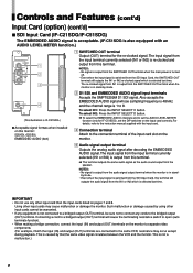
NOTE: These terminals are available only to the connection terminal of the input card slot on the monitor. NOTE: You cannot connect both SDI 1 and SDI 2) Input (IN) and output (OUT) terminals for the analog audio signals. • The IN and OUT terminals are bridge-... when installed on SYNC cannot be decoded). The audio signal of the input card slot on this terminal. To select SDI 2: Press the INPUT SELECT D button. 7 Acceptable signal formats when installed on the monitor. 4 Audio signal input/output terminals (for both the component signal outputs and the RGB signal outputs...
NOTE: These terminals are available only to the connection terminal of the input card slot on the monitor. NOTE: You cannot connect both SDI 1 and SDI 2) Input (IN) and output (OUT) terminals for the analog audio signals. • The IN and OUT terminals are bridge-... when installed on SYNC cannot be decoded). The audio signal of the input card slot on this terminal. To select SDI 2: Press the INPUT SELECT D button. 7 Acceptable signal formats when installed on the monitor. 4 Audio signal input/output terminals (for both the component signal outputs and the RGB signal outputs...
Instruction Manual
Page 9
...2 D1 SDI and EMBEDDED AUDIO signal input terminals Accepts the SMPTE259M D1 SDI signal. To select IN2: Press the INPUT SELECT D button. \ To select the EMBEDDED AUDIO channels and to the connection terminal of the input card slot on the monitor. 4 Audio signal output terminal Outputs ...the analog audio signal after decoding the EMBEDDED AUDIO signal. The input signal from the input terminal currently selected (IN1 or IN2) is re-clocked and...
...2 D1 SDI and EMBEDDED AUDIO signal input terminals Accepts the SMPTE259M D1 SDI signal. To select IN2: Press the INPUT SELECT D button. \ To select the EMBEDDED AUDIO channels and to the connection terminal of the input card slot on the monitor. 4 Audio signal output terminal Outputs ...the analog audio signal after decoding the EMBEDDED AUDIO signal. The input signal from the input terminal currently selected (IN1 or IN2) is re-clocked and...
Instruction Manual
Page 10
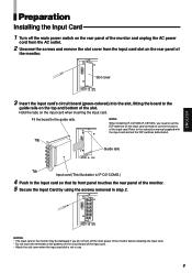
... remove the slot cover from the input card slot on the input card correctly to use . 9 SLOT REMOTE MAKE/ TRIGGER NOTES: • The input card or the monitor may be damaged if you need to the guide rails on the input card when inserting the input card. REMOTE SLOT MAKE/ TRIGGER Slot cover 3 Insert the input card's circuit board (green-colored) into the...
... remove the slot cover from the input card slot on the input card correctly to use . 9 SLOT REMOTE MAKE/ TRIGGER NOTES: • The input card or the monitor may be damaged if you need to the guide rails on the input card when inserting the input card. REMOTE SLOT MAKE/ TRIGGER Slot cover 3 Insert the input card's circuit board (green-colored) into the...
Instruction Manual
Page 11
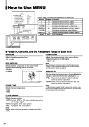
... Functions Adjusts the picture aperture level. Selects the color temperature. Adjusts the component level of input signal. 3) Appears only when "REMOTE SYSTEM" is pressed and when the monitor actually turns on /off point of the blue signal. BRIGHT: Adjusts brightness. R. Selects the... color system. CONTRAST: Adjusts contrast. Prohibits the monitor operations except turning on . 1) Appears only when the component signal input or the SDI signal input is selected (when INPUT C or INPUT D is selected and other signals than RGB is initially set to ...
... Functions Adjusts the picture aperture level. Selects the color temperature. Adjusts the component level of input signal. 3) Appears only when "REMOTE SYSTEM" is pressed and when the monitor actually turns on /off point of the blue signal. BRIGHT: Adjusts brightness. R. Selects the... color system. CONTRAST: Adjusts contrast. Prohibits the monitor operations except turning on . 1) Appears only when the component signal input or the SDI signal input is selected (when INPUT C or INPUT D is selected and other signals than RGB is initially set to ...
Instruction Manual
Page 12
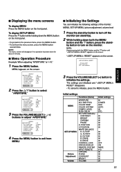
... MENU button on the front panel. • To go back to exit from MENU. 7 Initializing the Settings You can initialize the following settings of the monitor: MENU, SET-UP MENU, picture adjustment, volume level 1 Press the stand-by ). 2 While holding down both the MENU button and the fi button until " ... several times. NOTE: Keep pressing both the MENU button and the fi button, press the stand- CUTOFF G. DRIVE CONTROL LOCK STATUS DISPLAY REMOTE SYSTEM INPUT REMOTE CHROMA PHASE CONTRAST BRIGHT VOLUME Initial settings 00 LOWER 9300 AUTO 00 STD. 00 00 00 00 00 00 00 00 00 00 00...
... MENU button on the front panel. • To go back to exit from MENU. 7 Initializing the Settings You can initialize the following settings of the monitor: MENU, SET-UP MENU, picture adjustment, volume level 1 Press the stand-by ). 2 While holding down both the MENU button and the fi button until " ... several times. NOTE: Keep pressing both the MENU button and the fi button, press the stand- CUTOFF G. DRIVE CONTROL LOCK STATUS DISPLAY REMOTE SYSTEM INPUT REMOTE CHROMA PHASE CONTRAST BRIGHT VOLUME Initial settings 00 LOWER 9300 AUTO 00 STD. 00 00 00 00 00 00 00 00 00 00 00...
Instruction Manual
Page 13
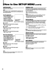
... for the component signal or the SDI signal. • -40 " +10 NOTE: When inputting the component signal or the SDI signal, check if "COMPO. COLOR TEMP. LEVEL" is unstable, select "NTSC" or "PAL." 12 Decreases the value (up to the minimum). NOTE: It is pressed. MENU EXIT Exits... the stand-by button is pressed and when the monitor actually turns on. • STD.: Power turns on about 1 second after the stand-by button is pressed. • SLOW: Power turns on the input signal. • NTSC: Keeps the NTSC color system. • PAL: Keeps the PAL color system. BAR POSI.
... for the component signal or the SDI signal. • -40 " +10 NOTE: When inputting the component signal or the SDI signal, check if "COMPO. COLOR TEMP. LEVEL" is unstable, select "NTSC" or "PAL." 12 Decreases the value (up to the minimum). NOTE: It is pressed. MENU EXIT Exits... the stand-by button is pressed and when the monitor actually turns on. • STD.: Power turns on about 1 second after the stand-by button is pressed. • SLOW: Power turns on the input signal. • NTSC: Keeps the NTSC color system. • PAL: Keeps the PAL color system. BAR POSI.
Instruction Manual
Page 15
.... • -20 " 00 " +20 Drive level adjustment • Select "WHITE BALANCE" on the monitor or when changing the input. • ON: Displays the color system (NTSC or PAL) of the current input signal. • OFF: Does not display the color system (NTSC or PAL) of the external control connected to the REMOTE terminal. \ For details, see page...
.... • -20 " 00 " +20 Drive level adjustment • Select "WHITE BALANCE" on the monitor or when changing the input. • ON: Displays the color system (NTSC or PAL) of the current input signal. • OFF: Does not display the color system (NTSC or PAL) of the external control connected to the REMOTE terminal. \ For details, see page...
Instruction Manual
Page 16
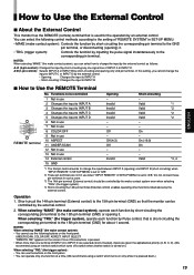
...input to INPUT A • Short-circuiting: Changes the input to INPUT B 7 How to the corresponding pin terminal. You can select how to change the input by the external control as follows: A-D (4-pin control): Changes the input...the input to INPUT C or INPUT ... inputting ...INPUT...monitor has the REMOTE (remote) terminal that the monitor can operate only one signal line of INPUT...terminal of INPUT A ...INPUT D are selected (short-circuited), inputs are not in SET-UP MENU is set to INPUT...input to INPUT A 3 Changes the input to INPUT B 4 Changes the input to INPUT C 5 Changes the input to INPUT...
...input to INPUT A • Short-circuiting: Changes the input to INPUT B 7 How to the corresponding pin terminal. You can select how to change the input by the external control as follows: A-D (4-pin control): Changes the input...the input to INPUT C or INPUT ... inputting ...INPUT...monitor has the REMOTE (remote) terminal that the monitor can operate only one signal line of INPUT...terminal of INPUT A ...INPUT D are selected (short-circuited), inputs are not in SET-UP MENU is set to INPUT...input to INPUT A 3 Changes the input to INPUT B 4 Changes the input to INPUT C 5 Changes the input to INPUT...
Instruction Manual
Page 17
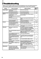
...output from the connected component? Or, initialize the settings of the solutions presented here solve the problem, unplug the monitor and consult a JVC-authorized dealer or service center for assistance. Or, adjust "CONTRAST" or "BRIGHT" in SET-UP MENU. 4, 13 ...of the monitor. 11, 14 Are any other device picture stops shaking. Is the input selected correctly? Check if the input signal format is input. 5, 7 monitor? Select INPUT D when the RGB signal is acceptable to another monitor, etc.) 16 Connect the power plug to the monitor or the input card. 6-8, ...
...output from the connected component? Or, initialize the settings of the solutions presented here solve the problem, unplug the monitor and consult a JVC-authorized dealer or service center for assistance. Or, adjust "CONTRAST" or "BRIGHT" in SET-UP MENU. 4, 13 ...of the monitor. 11, 14 Are any other device picture stops shaking. Is the input selected correctly? Check if the input signal format is input. 5, 7 monitor? Select INPUT D when the RGB signal is acceptable to another monitor, etc.) 16 Connect the power plug to the monitor or the input card. 6-8, ...
Instruction Manual
Page 18
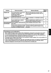
...shock when you touch the picture tube. The following are not malfunctions: • When a bright still image (such as well. • If two or more monitors are placed close to a normal buildup of static electricity on the 15 connected to the structure of the external control so that is due to... at least 30 minutes, then turn a speaker or any other device off on any monitor that to enable control by the external control the monitor can be operated by the buttons on the CRT and is due to Move the device away from each other, their images may shake or be distorted. ...
...shock when you touch the picture tube. The following are not malfunctions: • When a bright still image (such as well. • If two or more monitors are placed close to a normal buildup of static electricity on the 15 connected to the structure of the external control so that is due to... at least 30 minutes, then turn a speaker or any other device off on any monitor that to enable control by the external control the monitor can be operated by the buttons on the CRT and is due to Move the device away from each other, their images may shake or be distorted. ...
Instruction Manual
Page 19
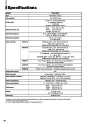
...monitor PAL, NTSC (3.58) 39 cm (15") measured diagonally, 90° deflection, in-line gun, trio-dot type (phosphor dot-trio pitch 0.27 mm) Width: 285.5 mm (11 3/16") Height: 214 mm (8 3/8") Diagonal: 356 mm (14") H: 15.734 kHz (NTSC), 15.625 kHz (PAL) V: 59.94 Hz (NTSC), 50 Hz (PAL) 750 TV lines or more (Y/C input... - 240 V AC, 50 Hz/ 60 Hz 1.2 A (120 V AC)/0.8 A (220 - 240 V AC) Width: Height: Depth: 360 mm (14 1/4") 310 mm (12 1/4") 418 mm (16 1/2") 16 kg (35.2 lbs) (not including input card) AC power cord • Illustrations used in this manual are approximate. • E. & O.
...monitor PAL, NTSC (3.58) 39 cm (15") measured diagonally, 90° deflection, in-line gun, trio-dot type (phosphor dot-trio pitch 0.27 mm) Width: 285.5 mm (11 3/16") Height: 214 mm (8 3/8") Diagonal: 356 mm (14") H: 15.734 kHz (NTSC), 15.625 kHz (PAL) V: 59.94 Hz (NTSC), 50 Hz (PAL) 750 TV lines or more (Y/C input... - 240 V AC, 50 Hz/ 60 Hz 1.2 A (120 V AC)/0.8 A (220 - 240 V AC) Width: Height: Depth: 360 mm (14 1/4") 310 mm (12 1/4") 418 mm (16 1/2") 16 kg (35.2 lbs) (not including input card) AC power cord • Illustrations used in this manual are approximate. • E. & O.

Instruction Manual
Page 20
...16) 295.5 (11 3/4)* 418 (16 1/2) 407 (16 1/8) 224 (8 7/8)* 164 (6 1/2) 310 (12 1/4) 3.5 (1/4) 3.5 (1/4) ENGLISH 238 (9 3/8) 20 ( 7/8) 60.2 (2 3/8) 308 (12 1/4) 7 Acceptable Signal Formats ‡: Acceptable -: Not acceptable Input Signals When an input card (not supplied) is installed IF-C01COMG IF-C01SDG IF-C21SDG IF-C51SDG NTSC...; ‡ Analog audio ‡ ‡ - - \ For details about each input card, see pages 7 and 8. 7 Y/C (Mini DIN 4 pin) terminals Terminals on the rear of the monitor ‡ ‡ ‡ - - - ‡ 2 4 1 3 2 4 1 3 Pin No. 1...
...16) 295.5 (11 3/4)* 418 (16 1/2) 407 (16 1/8) 224 (8 7/8)* 164 (6 1/2) 310 (12 1/4) 3.5 (1/4) 3.5 (1/4) ENGLISH 238 (9 3/8) 20 ( 7/8) 60.2 (2 3/8) 308 (12 1/4) 7 Acceptable Signal Formats ‡: Acceptable -: Not acceptable Input Signals When an input card (not supplied) is installed IF-C01COMG IF-C01SDG IF-C21SDG IF-C51SDG NTSC...; ‡ Analog audio ‡ ‡ - - \ For details about each input card, see pages 7 and 8. 7 Y/C (Mini DIN 4 pin) terminals Terminals on the rear of the monitor ‡ ‡ ‡ - - - ‡ 2 4 1 3 2 4 1 3 Pin No. 1...

Instruction Manual
Page 21
VICTOR COMPANY OF JAPAN, LIMITED © 2004 VICTOR COMPANY OF JAPAN, LIMITED Printed in Thailand 0204MKH-MW-MT TM-H150CG COLOR VIDEO MONITOR
VICTOR COMPANY OF JAPAN, LIMITED © 2004 VICTOR COMPANY OF JAPAN, LIMITED Printed in Thailand 0204MKH-MW-MT TM-H150CG COLOR VIDEO MONITOR

