

Instruction Manual
Page 4
... power cord or plug is in damage and will often require extensive work by the manufacturer that the appliance is damaged or frayed. If the appliance has been exposed to qualified service personnel under the following the operating instructions. c. f. Unauthorized substitutions may result in safe operating condition. Adjust only those controls that are required, be sure the service technician has used replacement parts...
... power cord or plug is in damage and will often require extensive work by the manufacturer that the appliance is damaged or frayed. If the appliance has been exposed to qualified service personnel under the following the operating instructions. c. f. Unauthorized substitutions may result in safe operating condition. Adjust only those controls that are required, be sure the service technician has used replacement parts...

Instruction Manual
Page 6
... the receiver is no guarantee that may cause undesired operation. Consult the dealer or an experienced radio/TV technician for a Class B digital device, pursuant to which can radiate radio frequency energy and, if not installed and used in accordance with Part 15 of the FCC Rules. CAUTION CHANGES OR MODIFICATIONS NOT APPROVED BY JVC KENWOOD Corporation COULD VOID USER...
... the receiver is no guarantee that may cause undesired operation. Consult the dealer or an experienced radio/TV technician for a Class B digital device, pursuant to which can radiate radio frequency energy and, if not installed and used in accordance with Part 15 of the FCC Rules. CAUTION CHANGES OR MODIFICATIONS NOT APPROVED BY JVC KENWOOD Corporation COULD VOID USER...
Instruction Manual
Page 9
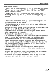
... USA), Isolated power supply only (For Europe). v Rating label is not strong enough to your dealer for Burglar Alarm Functionality. Please refer to support the weight, be in failure or fires. Pay careful attention during installation. v Do not install the camera near lighting fixtures of this manual of the camera unit. Check that the screws are not tightened securely. v When mounting this product.
... USA), Isolated power supply only (For Europe). v Rating label is not strong enough to your dealer for Burglar Alarm Functionality. Please refer to support the weight, be in failure or fires. Pay careful attention during installation. v Do not install the camera near lighting fixtures of this manual of the camera unit. Check that the screws are not tightened securely. v When mounting this product.

Instruction Manual
Page 10
Contents Contents Introduction Safety Precautions 2 Contents 10 Features 11 Operating Precautions 12 Name of Parts 15 Connection/Installation Connection 17 Mounting the Camera 20 Setting/Adjustment Switch Settings 22 Adjusting Image 23 Checking after Operation 25 Adjusting the Auto White Balance 26 Menu Setting The Flow of Menu Screen 28 Menu Setting Procedure 30 BASIC MENU 31 ADVANCED MENU 33 Setting Examples Manual Adjustment of White Balance 41 Setting the Privacy Mask 42 Settings in Dark Locations 43 Others Specifications 46 E-10
Contents Contents Introduction Safety Precautions 2 Contents 10 Features 11 Operating Precautions 12 Name of Parts 15 Connection/Installation Connection 17 Mounting the Camera 20 Setting/Adjustment Switch Settings 22 Adjusting Image 23 Checking after Operation 25 Adjusting the Auto White Balance 26 Menu Setting The Flow of Menu Screen 28 Menu Setting Procedure 30 BASIC MENU 31 ADVANCED MENU 33 Setting Examples Manual Adjustment of White Balance 41 Setting the Privacy Mask 42 Settings in Dark Locations 43 Others Specifications 46 E-10
Instruction Manual
Page 11
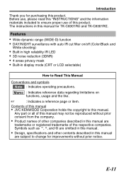
... copyright to this manual are subject to change for purchasing this product. Symbols such as , E , T and © are omitted in this manual are trademarks or registered trademarks of this manual for TK-C8301RU and TK-C8301RE. Before use of the respective companies. A : Indicates a reference page or item. v Design, specifications and other companies described in this manual. The instructions in display mode (CRT or...
... copyright to this manual are subject to change for purchasing this product. Symbols such as , E , T and © are omitted in this manual are trademarks or registered trademarks of this manual for TK-C8301RU and TK-C8301RE. Before use of the respective companies. A : Indicates a reference page or item. v Design, specifications and other companies described in this manual. The instructions in display mode (CRT or...

Instruction Manual
Page 12
... time, turn off the power for indoor use an outdoor camera housing (optional). m Energy Conservation v When the camera is subject to fog. In a place at which is not in its color. v Using this unit in the vicinity of the transmitting antenna of a radio or TV, devices that emit strong electromagnetic waves such as a transformer or motor, or wireless devices such as vehicle installation...
... time, turn off the power for indoor use an outdoor camera housing (optional). m Energy Conservation v When the camera is subject to fog. In a place at which is not in its color. v Using this unit in the vicinity of the transmitting antenna of a radio or TV, devices that emit strong electromagnetic waves such as a transformer or motor, or wireless devices such as vehicle installation...

Instruction Manual
Page 15
... 20) C Camera-mounting bracket fastening screws (M2.6 x 6 mm) (A page 20) D Camera-mounting screw hole (A page 20) E Lens Cover (A page 23) F Power Supply Terminal (A page 17) G Selector Switch (A page 22) H Alarm Input/Output Terminal (A page 19) I [VIDEO OUT] Monitor Terminal (A page 18) J [J / K / H / I] Button (A page 22, 26, 30) K [SET] Button (A page 26, 30) L [MENU] Button (A page 26, 30) M Fall Prevention Wire Screw (M3 x 6mm) (A page 21) E-15 Name of Parts Camera GH IJ...
... 20) C Camera-mounting bracket fastening screws (M2.6 x 6 mm) (A page 20) D Camera-mounting screw hole (A page 20) E Lens Cover (A page 23) F Power Supply Terminal (A page 17) G Selector Switch (A page 22) H Alarm Input/Output Terminal (A page 19) I [VIDEO OUT] Monitor Terminal (A page 18) J [J / K / H / I] Button (A page 22, 26, 30) K [SET] Button (A page 26, 30) L [MENU] Button (A page 26, 30) M Fall Prevention Wire Screw (M3 x 6mm) (A page 21) E-15 Name of Parts Camera GH IJ...

Instruction Manual
Page 17
... Connection/Installation Connection To the terminal of door switch etc. D/N AUTO OFF BLC OFF ON LCD CRT WIDE-D ON OFF MONITOR TYPE CLASS 2 ONLY (U TYPE) ISOLATED POWER ONLY (E TYPE) AUX GND SEE INSTRUCTION MANUAL VIDEO OUT FOCUS ADJUST SET DC12V 1 2 AC24V MENU Monitor (A page 18) Connect to the terminal. m AC24 V or DC12 V To prevent connection errors or a cable disconnection, use a lug plate to connect to AC 24V or DC 12V power supply . Connecting the Power Supply Cable...
... Connection/Installation Connection To the terminal of door switch etc. D/N AUTO OFF BLC OFF ON LCD CRT WIDE-D ON OFF MONITOR TYPE CLASS 2 ONLY (U TYPE) ISOLATED POWER ONLY (E TYPE) AUX GND SEE INSTRUCTION MANUAL VIDEO OUT FOCUS ADJUST SET DC12V 1 2 AC24V MENU Monitor (A page 18) Connect to the terminal. m AC24 V or DC12 V To prevent connection errors or a cable disconnection, use a lug plate to connect to AC 24V or DC 12V power supply . Connecting the Power Supply Cable...

Instruction Manual
Page 18
... same time. v Do not connect DC 12 V and AC 24 V cables at its maximum power consumption. If voltage drop occurs during operation, the performance will occur when the camera is connected by mistake, the internal circuit may be damaged. v When using a DC 12 V power supply, ensure that the polarities of the cable are used, the resistance of camera to below 10 %. Connecting the Monitor Connect with...
... same time. v Do not connect DC 12 V and AC 24 V cables at its maximum power consumption. If voltage drop occurs during operation, the performance will occur when the camera is connected by mistake, the internal circuit may be damaged. v When using a DC 12 V power supply, ensure that the polarities of the cable are used, the resistance of camera to below 10 %. Connecting the Monitor Connect with...

Instruction Manual
Page 19
... a polarity. Connection/Installation Connecting the Alarm Input/Output Terminal Menu settings may not be required depending on the connected equipment. (A page 40) The default setting has been set to connect such that the alarm signal stays at a minimum of 200 ms or more. D/N AUTO OFF BLC OFF ON LCD CRT WIDE-D ON OFF MONITOR TYPE CLASS 2 ONLY (U TYPE) ISOLATED POWER ONLY (E TYPE) SEE INSTRUCTION MANUAL VIDEO OUT FOCUS ADJUST SET AUX(IN...
... a polarity. Connection/Installation Connecting the Alarm Input/Output Terminal Menu settings may not be required depending on the connected equipment. (A page 40) The default setting has been set to connect such that the alarm signal stays at a minimum of 200 ms or more. D/N AUTO OFF BLC OFF ON LCD CRT WIDE-D ON OFF MONITOR TYPE CLASS 2 ONLY (U TYPE) ISOLATED POWER ONLY (E TYPE) SEE INSTRUCTION MANUAL VIDEO OUT FOCUS ADJUST SET AUX(IN...

Instruction Manual
Page 20
... the camera. 2 Mount the camera-mounting bracket on top of the camera. 3 Mount the camera onto a fixer, pan/tilt unit and the like , use a screw that is originally mounted at the bottom of the camera before shipment but it can also be mounted on top of the camera. 1 Remove the camera-mounting bracket fastening screws (x2). .. Use camera-mounting bracket fastening screws with a length shorter than 6 mm. Connection/Installation Mounting the Camera When mounting the camera on a fixer, pan/tilt and...
... the camera. 2 Mount the camera-mounting bracket on top of the camera. 3 Mount the camera onto a fixer, pan/tilt unit and the like , use a screw that is originally mounted at the bottom of the camera before shipment but it can also be mounted on top of the camera. 1 Remove the camera-mounting bracket fastening screws (x2). .. Use camera-mounting bracket fastening screws with a length shorter than 6 mm. Connection/Installation Mounting the Camera When mounting the camera on a fixer, pan/tilt and...

Instruction Manual
Page 21
... or accidents may damage the internal parts. 6mm6 mm 2 mm OFF D/N AUTO ON BLC OFF CRT LCD ON WIDE-D OFF MONITOR TYPE CLASS(U2TOYNPLEY) ISOONLALYTE(ED TPYOPWEE) R AUX GND SEE INSTRUCTMIOANNUAL VIDEO OUT FOCUS ADJUST SET MENU DC12V 2 AC24V 1 Fall prevention wire M3 x 6 mm . v When installing the camera on the back of the camera for the installation of the fall . Ask a professional to...
... or accidents may damage the internal parts. 6mm6 mm 2 mm OFF D/N AUTO ON BLC OFF CRT LCD ON WIDE-D OFF MONITOR TYPE CLASS(U2TOYNPLEY) ISOONLALYTE(ED TPYOPWEE) R AUX GND SEE INSTRUCTMIOANNUAL VIDEO OUT FOCUS ADJUST SET MENU DC12V 2 AC24V 1 Fall prevention wire M3 x 6 mm . v When installing the camera on the back of the camera for the installation of the fall . Ask a professional to...

Instruction Manual
Page 22
... J button to color at all times when "OFF" is set in [BLC AREA] of the menu. (Default setting: OFF) C [MONITOR TYPE LCD/CRT] Monitor Type Selector Switch Set this is selected. The image is set to open the lens iris for easy focusing. (A page 24) E-22 Setting/Adjustment Switch Settings A B C D D/N AUTO OFF BLC OFF ON LCD CRT WIDE-D ON OFF MONITOR TYPE CLASS 2 ONLY (U TYPE) ISOLATED POWER ONLY (E TYPE) AUX GND SEE INSTRUCTION MANUAL VIDEO...
... J button to color at all times when "OFF" is set in [BLC AREA] of the menu. (Default setting: OFF) C [MONITOR TYPE LCD/CRT] Monitor Type Selector Switch Set this is selected. The image is set to open the lens iris for easy focusing. (A page 24) E-22 Setting/Adjustment Switch Settings A B C D D/N AUTO OFF BLC OFF ON LCD CRT WIDE-D ON OFF MONITOR TYPE CLASS 2 ONLY (U TYPE) ISOLATED POWER ONLY (E TYPE) AUX GND SEE INSTRUCTION MANUAL VIDEO...

Instruction Manual
Page 23
... not pull the lens cover too hard. The fall prevention sheet may cause the camera to malfunction. 1 1 Remove the lens cover. ① Press the mark of the lens cover (either left /right. Adjust the image size by touching the metallic part of the catches from the camera. ② Remove another catch from the camera. Setting/Adjustment Adjusting Image After mounting the camera, adjust the images while looking at the...
... not pull the lens cover too hard. The fall prevention sheet may cause the camera to malfunction. 1 1 Remove the lens cover. ① Press the mark of the lens cover (either left /right. Adjust the image size by touching the metallic part of the catches from the camera. ② Remove another catch from the camera. Setting/Adjustment Adjusting Image After mounting the camera, adjust the images while looking at the...

Instruction Manual
Page 26
... changed, adjust the white balance again. 1 Press the [MENU] button. 2 Select [WHITE BALANCE] with the [J / K] button and "AWC" with the [H / I button D/N AUTO OFF BLC OFF ON LCD CRT WIDE-D ON OFF MONITOR TYPE CLASS 2 ONLY (U TYPE) ISOLATED POWER ONLY (E TYPE) AUX GND SEE INSTRUCTION MANUAL VIDEO OUT FOCUS ADJUST SET DC12V 1 2 AC24V MENU SET button MENU button WHITE BALANCE CONTROL E AWC SET R GAIN 160 B GAIN 160 WHITE BALANCE CONTROL E AWC SET R GAIN 160 B GAIN 160 AWC OPERATION AWC OPERATION (during operation...
... changed, adjust the white balance again. 1 Press the [MENU] button. 2 Select [WHITE BALANCE] with the [J / K] button and "AWC" with the [H / I button D/N AUTO OFF BLC OFF ON LCD CRT WIDE-D ON OFF MONITOR TYPE CLASS 2 ONLY (U TYPE) ISOLATED POWER ONLY (E TYPE) AUX GND SEE INSTRUCTION MANUAL VIDEO OUT FOCUS ADJUST SET DC12V 1 2 AC24V MENU SET button MENU button WHITE BALANCE CONTROL E AWC SET R GAIN 160 B GAIN 160 WHITE BALANCE CONTROL E AWC SET R GAIN 160 B GAIN 160 AWC OPERATION AWC OPERATION (during operation...

Instruction Manual
Page 27
... ERROR : TIME OVER (Subject movement) Displayed when the subject moves. v AWC ERROR : NG (Subject error) Displayed when there is not enough white color on the subject or the color temperature is not successful, the following messages will appear on the monitor. Decrease the illumination, then readjust the white balance. Setting/Adjustment m Error display If auto white balance adjustment is not suitable. Fill the screen with a white object thoroughly and adjust the white...
... ERROR : TIME OVER (Subject movement) Displayed when the subject moves. v AWC ERROR : NG (Subject error) Displayed when there is not enough white color on the subject or the color temperature is not successful, the following messages will appear on the monitor. Decrease the illumination, then readjust the white balance. Setting/Adjustment m Error display If auto white balance adjustment is not suitable. Fill the screen with a white object thoroughly and adjust the white...
Instruction Manual
Page 31
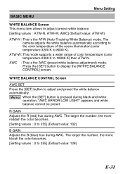
... : 0 to 255] (Default value: 128) E-31 WHITE BALANCE CONTROL Screen AWC SET Press the [SET] button to display the [WHITE BALANCE CONTROL] screen. ATW-W: This mode supports a wider range of the scene illumination (color temperature 3200 K to 8000 K). AWC : This is the ATW (Auto-Tracking White Balance) mode. BASIC MENU Menu Setting WHITE BALANCE Screen This menu item allows to adjust camera white balance. [Setting values : ATW-N, ATW-W, AWC] (Default value: ATW-W) ATW-N : This is the AWC (preset white balance adjustment) mode.
... : 0 to 255] (Default value: 128) E-31 WHITE BALANCE CONTROL Screen AWC SET Press the [SET] button to display the [WHITE BALANCE CONTROL] screen. ATW-W: This mode supports a wider range of the scene illumination (color temperature 3200 K to 8000 K). AWC : This is the ATW (Auto-Tracking White Balance) mode. BASIC MENU Menu Setting WHITE BALANCE Screen This menu item allows to adjust camera white balance. [Setting values : ATW-N, ATW-W, AWC] (Default value: ATW-W) ATW-N : This is the AWC (preset white balance adjustment) mode.
Instruction Manual
Page 37
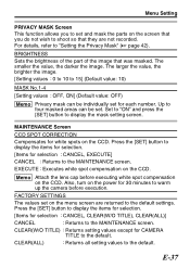
... each number. For details, refer to display the mask setting screen. Set to "ON" and press the [SET] button to "Setting the Privacy Mask" (A page 42). EXECUTE : Executes white spot compensation on the CCD. Menu Setting PRIVACY MASK Screen This function allows you to set and mask the parts on the screen that you do not wish to the default settings. BRIGHTNESS Sets the brightness of the part of the image...
... each number. For details, refer to display the mask setting screen. Set to "ON" and press the [SET] button to "Setting the Privacy Mask" (A page 42). EXECUTE : Executes white spot compensation on the CCD. Menu Setting PRIVACY MASK Screen This function allows you to set and mask the parts on the screen that you do not wish to the default settings. BRIGHTNESS Sets the brightness of the part of the image...
Instruction Manual
Page 40
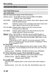
... of the text in the menu. [Setting values : NORMAL, DOUBLE] (Default value: DOUBLE) m TITLE COLOR (U model), TITLE COLOUR (E model) Sets the color of the title displayed when alarm signal is input. IN:D/N : Switches image to "DOUBLE", the text displayed will be selected. If D/N switch is OFF, "IN:D/N" can set to the color/black-and-white mode when alarm signal is changed to black-and-white. If D/N switch is changed to OFF during "IN...
... of the text in the menu. [Setting values : NORMAL, DOUBLE] (Default value: DOUBLE) m TITLE COLOR (U model), TITLE COLOUR (E model) Sets the color of the title displayed when alarm signal is input. IN:D/N : Switches image to "DOUBLE", the text displayed will be selected. If D/N switch is OFF, "IN:D/N" can set to the color/black-and-white mode when alarm signal is changed to black-and-white. If D/N switch is changed to OFF during "IN...

Instruction Manual
Page 43
... camera won 't turn on ). v When [AGC] in the menu setting is set to "OFF", operation error occurs and above setting values are examples of the recording locations. m Setting the displayed images (black and white or color) (Set in [D/N MODE]) Default setting is "AUTO", to the black and white images when the surrounding is dark (IR LED light on). E-43 Switches to the color images when the surrounding is bright (IR LED light off), and to switch the displayed images (Color/black and white) based...
... camera won 't turn on ). v When [AGC] in the menu setting is set to "OFF", operation error occurs and above setting values are examples of the recording locations. m Setting the displayed images (black and white or color) (Set in [D/N MODE]) Default setting is "AUTO", to the black and white images when the surrounding is dark (IR LED light on). E-43 Switches to the color images when the surrounding is bright (IR LED light off), and to switch the displayed images (Color/black and white) based...


