
Instruction Manual
Page 1
Model No. TK-C1460 Serial No. COLOUR VIDEO CAMERA TK-C1460 INSTRUCTIONS BF LOOK DIGITAL COLOR VIDEO CAMERA For Customer Use: Enter below the Serial No. SC961012H-001 (CD-ROM) E-1 Retain this information for future reference. which is located on the body.
Model No. TK-C1460 Serial No. COLOUR VIDEO CAMERA TK-C1460 INSTRUCTIONS BF LOOK DIGITAL COLOR VIDEO CAMERA For Customer Use: Enter below the Serial No. SC961012H-001 (CD-ROM) E-1 Retain this information for future reference. which is located on the body.

Instruction Manual
Page 5
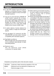
Thank you for purchasing this product. (These instrustions are for TK-C1460U and TK-C1460E) Before beginning to operate this unit, please read the instruction manual carefully in order to make sure that the best possible performance is obtained. ...Screen 35 FACTORY SETTINGS Screen 35 BLC EDITTING Screen ...36 Manual Adjustment of White Balance 37 CAMERA TITLE Setting ...38 Setting the MOTION DETECT Function 39 Output of Black-White/Color switching signal 40 Control by Black-White/Color switching signal from the outside 41 OTHERS Installing the ferrite core ...42 Specifications ...42 E-5
Thank you for purchasing this product. (These instrustions are for TK-C1460U and TK-C1460E) Before beginning to operate this unit, please read the instruction manual carefully in order to make sure that the best possible performance is obtained. ...Screen 35 FACTORY SETTINGS Screen 35 BLC EDITTING Screen ...36 Manual Adjustment of White Balance 37 CAMERA TITLE Setting ...38 Setting the MOTION DETECT Function 39 Output of Black-White/Color switching signal 40 Control by Black-White/Color switching signal from the outside 41 OTHERS Installing the ferrite core ...42 Specifications ...42 E-5
Instruction Manual
Page 6
...installation due to shoot both bright and dark locations. Ⅲ The use of a new CCD with diversified systems. Ⅲ Day/Night surveillance When the light is low, the camera pictures can be switched automatically to black and white pictures. Ⅲ Electronic zoom The ...Furthermore, we do not accept any damage to the camera in cases when it becoming impossible to record due to a problem in this instruction manual. E-6 INTRODUCTION Features Ⅲ A new DSP (Digital Signal Processor) features a Extended Dynamic Range (ExDR) and enables to not observing the installation instructions...
...installation due to shoot both bright and dark locations. Ⅲ The use of a new CCD with diversified systems. Ⅲ Day/Night surveillance When the light is low, the camera pictures can be switched automatically to black and white pictures. Ⅲ Electronic zoom The ...Furthermore, we do not accept any damage to the camera in cases when it becoming impossible to record due to a problem in this instruction manual. E-6 INTRODUCTION Features Ⅲ A new DSP (Digital Signal Processor) features a Extended Dynamic Range (ExDR) and enables to not observing the installation instructions...

Instruction Manual
Page 7
...TK-C1460U Class 2 only TK-C1460E Isolated power supply only ● Caution for indoor use camera more than three meters apart from the actual colours due to the operational principles of the CCD..., and is not a defect. ● Observe the following places. • In a place exposed to rain or moisture. • In a place with vapor or oil soot, for example in a kitchen. • When the ambient temperature rises above or falls below the acceptable range...You may hear some noise when the screen is switched between the color and the black and white, because the optical filter moves. As...
...TK-C1460U Class 2 only TK-C1460E Isolated power supply only ● Caution for indoor use camera more than three meters apart from the actual colours due to the operational principles of the CCD..., and is not a defect. ● Observe the following places. • In a place exposed to rain or moisture. • In a place with vapor or oil soot, for example in a kitchen. • When the ambient temperature rises above or falls below the acceptable range...You may hear some noise when the screen is switched between the color and the black and white, because the optical filter moves. As...

Instruction Manual
Page 8
... × 6 mm) Be sure to the circumstance. To re-attach the bracket use of the camera before shipment. E-8 When readjustment is applicable to prevent any fall when mounting the camera. This is required, loosen the locking screw 3 by turning it counterclockwise and turn the back focus ...(Use a 7mm screw shorter than 7 mm.) 6 Rotation-preventive hole Make use the threaded holes at the top, with the camera mounting bracket fixing screws 7 . 5 Camera-mounting screw hole (1/4 -20UNC) Use this rotation-preventive hole to both the C-mount lenses and CS-mount lenses. 2 Back focus...
... × 6 mm) Be sure to the circumstance. To re-attach the bracket use of the camera before shipment. E-8 When readjustment is applicable to prevent any fall when mounting the camera. This is required, loosen the locking screw 3 by turning it counterclockwise and turn the back focus ...(Use a 7mm screw shorter than 7 mm.) 6 Rotation-preventive hole Make use the threaded holes at the top, with the camera mounting bracket fixing screws 7 . 5 Camera-mounting screw hole (1/4 -20UNC) Use this rotation-preventive hole to both the C-mount lenses and CS-mount lenses. 2 Back focus...

Instruction Manual
Page 9
DC: In case of lens without EE amp built-in. ( ) At time of factory shipment VIDEO: TK-C1460E DC: TK-C1460U 10 [IRIS] Iris Terminal This is connected to display a submenu. (੬ Page 23) AWC: If this button is brought up. (੬ Page 23) 12 [SET/... Switch This is set according to make fine adjustments on the set , even if colour temperature changes, white balance does not change. ! @# $ SET AWC MENU CAMERA SETUP EXT TERM-OFF INT/GL DUPLEX RX TERM-OFF NOT USED ON LL SIMPLEX ON % ^ & * VIDEO IRIS DC 8 90 8 Cover The cover opens if...
DC: In case of lens without EE amp built-in. ( ) At time of factory shipment VIDEO: TK-C1460E DC: TK-C1460U 10 [IRIS] Iris Terminal This is connected to display a submenu. (੬ Page 23) AWC: If this button is brought up. (੬ Page 23) 12 [SET/... Switch This is set according to make fine adjustments on the set , even if colour temperature changes, white balance does not change. ! @# $ SET AWC MENU CAMERA SETUP EXT TERM-OFF INT/GL DUPLEX RX TERM-OFF NOT USED ON LL SIMPLEX ON % ^ & * VIDEO IRIS DC 8 90 8 Cover The cover opens if...
Instruction Manual
Page 10
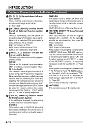
...INT/GL, LL] Selector Switch for internal synchronization (INT) or external synchronization (GL). INT/GL: This is set this switch of the camera. When switching between multiple cameras using a switcher, selecting this is switched ON, termination is switched. (This cannot be used in a duplex system (two-way). E-...the transmission between RX + and RX - If the system including the camera is the M.DROP (Multi-drop, RS-485) system, only the camera mounted at the value of control signal cable is 60 Hz (50 Hz) ( ):TK-C1460U) (INT/GL: At time of factory shipment) 18 NOT USED This...
...INT/GL, LL] Selector Switch for internal synchronization (INT) or external synchronization (GL). INT/GL: This is set this switch of the camera. When switching between multiple cameras using a switcher, selecting this is switched ON, termination is switched. (This cannot be used in a duplex system (two-way). E-...the transmission between RX + and RX - If the system including the camera is the M.DROP (Multi-drop, RS-485) system, only the camera mounted at the value of control signal cable is 60 Hz (50 Hz) ( ):TK-C1460U) (INT/GL: At time of factory shipment) 18 NOT USED This...
Instruction Manual
Page 11
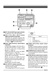
... signal. • Pin configuration of an external sync signal such as a composite video (VBS) or black burst (BB) signal. To terminate this to the camera. 25 [SYNC IN] Sync signal input connector This BNC connector accepts the input of Y/C OUT connector 4 3 2 1 Pin No. 1 2 3 4 Signal...] Video signal output connector This BNC connector outputs a composite video signal. When a sync signal is input into this connector, the camera operation is automatically synchronized with electrical characteristics conforming to the EIA/TIA RS-422A or RS-485 standard. (੬ Page 10 17 RX...
... signal. • Pin configuration of an external sync signal such as a composite video (VBS) or black burst (BB) signal. To terminate this to the camera. 25 [SYNC IN] Sync signal input connector This BNC connector accepts the input of Y/C OUT connector 4 3 2 1 Pin No. 1 2 3 4 Signal...] Video signal output connector This BNC connector outputs a composite video signal. When a sync signal is input into this connector, the camera operation is automatically synchronized with electrical characteristics conforming to the EIA/TIA RS-422A or RS-485 standard. (੬ Page 10 17 RX...
Instruction Manual
Page 12
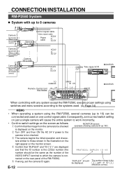
... cameras (up to 8 cameras Av Pk L ALC L Camera 1 MACHINE ID:1 (Menu screen) RX TERM: OFF (switch) Av Pk L H ALC LEVEL Camera TK-C1460 Camera TK-C1460 Control signal cable Video signal cable Power cable AC24V or DC12V Camera 2 MACHINE ID:2 (Menu screen) RX TERM: OFF (switch) Camera TK-C1460... AC24V or DC12V Av Pk L H ALC LEVEL Camera 8 MACHINE ID:8 (Menu screen) RX TERM: ...
... cameras (up to 8 cameras Av Pk L ALC L Camera 1 MACHINE ID:1 (Menu screen) RX TERM: OFF (switch) Av Pk L H ALC LEVEL Camera TK-C1460 Camera TK-C1460 Control signal cable Video signal cable Power cable AC24V or DC12V Camera 2 MACHINE ID:2 (Menu screen) RX TERM: OFF (switch) Camera TK-C1460... AC24V or DC12V Av Pk L H ALC LEVEL Camera 8 MACHINE ID:8 (Menu screen) RX TERM: ...
Instruction Manual
Page 13
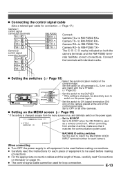
... ON Set this switch to the DUPLEX * If the setting is changed , be used for loop connection. C OMMUN I C A T I O N S TYLE MACH I NE I D M. Camera RX+ to LL (Line Lock) and match with identical marks. The A B C D marks indicated on page 16. ● The control signal cable cannot be used . Set... item to OFF on all equipment to be absolutely sure to RM-P2580 TX- When connecting ● Turn OFF the power supply to all other cameras. Ⅲ Setting on the MENU screen (੬ Page 35) * If the setting is changed , escape from another machine, make sure that...
... ON Set this switch to the DUPLEX * If the setting is changed , be used for loop connection. C OMMUN I C A T I O N S TYLE MACH I NE I D M. Camera RX+ to LL (Line Lock) and match with identical marks. The A B C D marks indicated on page 16. ● The control signal cable cannot be used . Set... item to OFF on all equipment to be absolutely sure to RM-P2580 TX- When connecting ● Turn OFF the power supply to all other cameras. Ⅲ Setting on the MENU screen (੬ Page 35) * If the setting is changed , escape from another machine, make sure that...
Instruction Manual
Page 14
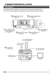
...according to be used before making carefully. 4.Setting the switches (੬ Page 10) 6.Back focus adjustment (੬ Page 21) Av Pk L H ALC LEVEL SET MENU CAMERA SETUP EXT TERM-OFF INT/GL DUPLEX RX TERM-OFF IOT USED ON LL SIMPLEX ON VIDEO DC 7.Auto white balance control adjustment (੬ Page... 22) 5.Lens adjustment (੬ Page 20) 3.Mounting the camera 1.Mounting the lens (੬ Page 18) (੬ Page 15) To controlling systems such as switches Monitor E-14 RX+ RX-
...according to be used before making carefully. 4.Setting the switches (੬ Page 10) 6.Back focus adjustment (੬ Page 21) Av Pk L H ALC LEVEL SET MENU CAMERA SETUP EXT TERM-OFF INT/GL DUPLEX RX TERM-OFF IOT USED ON LL SIMPLEX ON VIDEO DC 7.Auto white balance control adjustment (੬ Page... 22) 5.Lens adjustment (੬ Page 20) 3.Mounting the camera 1.Mounting the lens (੬ Page 18) (੬ Page 15) To controlling systems such as switches Monitor E-14 RX+ RX-
Instruction Manual
Page 15
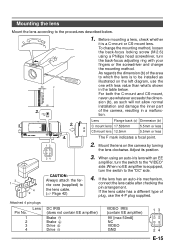
...-focus locking screw (M 2.6) using an auto-iris lens with your fingers or the screwdriver and change the mounting method. As regards the dimension (b) of the camera, resulting in the table below . Mounting the lens Mount the lens according to the procedures described below . Lens Flange back (c) Dimension (b) C mount lens 17.526mm... the lens is a C-mount or CS-mount lens. For both the C-mount and CS-mount, never use whatever exceeds the dimension (b), as illustrated on the camera by turning the lens clockwise.
...-focus locking screw (M 2.6) using an auto-iris lens with your fingers or the screwdriver and change the mounting method. As regards the dimension (b) of the camera, resulting in the table below . Mounting the lens Mount the lens according to the procedures described below . Lens Flange back (c) Dimension (b) C mount lens 17.526mm... the lens is a C-mount or CS-mount lens. For both the C-mount and CS-mount, never use whatever exceeds the dimension (b), as illustrated on the camera by turning the lens clockwise.

Instruction Manual
Page 16
...same time. • When using a DC 12 V power supply, ensure that 2-conductor VVF cables (vinyl-insulated vinyl sheath cables) are used . The following : TK-C1460U Class 2 only TK-C1460E Isolated power supply only E-16 CONNECTION/INSTALLATION Connections on the back Ⅲ Power supply (DC 12 V or AC 24 V) + - 1 2 Connect the DC... prevent connection errors or a cable disconnection, we recommend the use a thick cable to restrict the voltage drop at the camera side to below 10%, or place the power supply near to the DC 12V/AC 24V terminals. Either use of the cable are correct....
...same time. • When using a DC 12 V power supply, ensure that 2-conductor VVF cables (vinyl-insulated vinyl sheath cables) are used . The following : TK-C1460U Class 2 only TK-C1460E Isolated power supply only E-16 CONNECTION/INSTALLATION Connections on the back Ⅲ Power supply (DC 12 V or AC 24 V) + - 1 2 Connect the DC... prevent connection errors or a cable disconnection, we recommend the use a thick cable to restrict the voltage drop at the camera side to below 10%, or place the power supply near to the DC 12V/AC 24V terminals. Either use of the cable are correct....

Instruction Manual
Page 17
... pair cables is not possible with a signal containing too much jitter, such as a VCR or videodisc playback signal. • For details, consult a JVC authorized dealer. Connect to control the camera using the RS-442A or RS-485 signals. A TX+ B TX- Ⅲ Control signal cables These cables should be adjusted. MEMO • Genlocking...
... pair cables is not possible with a signal containing too much jitter, such as a VCR or videodisc playback signal. • For details, consult a JVC authorized dealer. Connect to control the camera using the RS-442A or RS-485 signals. A TX+ B TX- Ⅲ Control signal cables These cables should be adjusted. MEMO • Genlocking...
Instruction Manual
Page 18
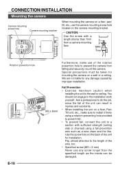
...M3 x 6mm • When installing the unit on a fixer, Pan/ Tilt unit, etc., make use the camera mounting screw hole located on the camera-mounting bracket. MAX. 7mm Rotation prevention hole Furthermore, make sure to install it firmly using a fall prevention wire ...chain and the like. E-18 CONNECTION/INSTALLATION Mounting the camera Camera mounting screw hole Camera-mounting bracket When mounting the camera on a fixer, pan/ tilt, etc., use of the rotation prevention hole to prevent the camera from a camera-mounting face. CAUTION: Use the screw with sufficient ...
...M3 x 6mm • When installing the unit on a fixer, Pan/ Tilt unit, etc., make use the camera mounting screw hole located on the camera-mounting bracket. MAX. 7mm Rotation prevention hole Furthermore, make sure to install it firmly using a fall prevention wire ...chain and the like. E-18 CONNECTION/INSTALLATION Mounting the camera Camera mounting screw hole Camera-mounting bracket When mounting the camera on a fixer, pan/ tilt, etc., use of the rotation prevention hole to prevent the camera from a camera-mounting face. CAUTION: Use the screw with sufficient ...

Instruction Manual
Page 19
...Tilt unit. • Mounting from the top Remove the CAMERA MOUNTING BRACKET from the bottom of camera • Mounting from the bottom This camera is originally designed to use a 6 mm long locking screw for the cameramounting bracket. (This camera is standard photographic panhead screw size (1/4-20 UNC). Be... sure to be mounted from the bottom, as shown q. Attach the CAMERA MOUNTING BRACKET to the top, then mount the camera on the Fixing Unit as shown w. Make sure that two original screws are used indoor and under similar conditions.)...
...Tilt unit. • Mounting from the top Remove the CAMERA MOUNTING BRACKET from the bottom of camera • Mounting from the bottom This camera is originally designed to use a 6 mm long locking screw for the cameramounting bracket. (This camera is standard photographic panhead screw size (1/4-20 UNC). Be... sure to be mounted from the bottom, as shown q. Attach the CAMERA MOUNTING BRACKET to the top, then mount the camera on the Fixing Unit as shown w. Make sure that two original screws are used indoor and under similar conditions.)...
Instruction Manual
Page 20
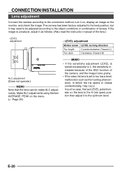
...iris open) position then adjust it to the optimum level. If the image is set LEVEL potentiometer on the monitor, and check the image. The camera has been factory-adjusted to the best position, but it as the hunting phenomenon, in which the iris opens or closes unintentionally, may need to... Note that the lens cannot make ALC adjustments. In such a case, first set to L, the sensitivity increases because of the AGC function of the camera, and the image looks grainy. • If the video iris lens is unnatural, adjust it may occur. Make ALC adjustments using the item AVERAGE:...
...iris open) position then adjust it to the optimum level. If the image is set LEVEL potentiometer on the monitor, and check the image. The camera has been factory-adjusted to the best position, but it as the hunting phenomenon, in which the iris opens or closes unintentionally, may need to... Note that the lens cannot make ALC adjustments. In such a case, first set to L, the sensitivity increases because of the AGC function of the camera, and the image looks grainy. • If the video iris lens is unnatural, adjust it may occur. Make ALC adjustments using the item AVERAGE:...

Instruction Manual
Page 21
... the image is released. (The ND filter acts to reduce the amount of focus when zooming (telephoto wide-angle), adjust the camera as follows. 1. Set the lens to the maximum wide-angle position, and turn the back focus ring to make accurate back focus adjustments, use the electronic shutter... wavelength band.) Back focus adjustment ring Tighten Loosen BF LOCK Back focus locking screw (M2.6) Lens focus ring MEMO Focus setting can differ on the color and on both screens. • With a fixed-focus lens If the focus can not be adjusted correctly by turning it counterclocckwise ( ) with a ...
... the image is released. (The ND filter acts to reduce the amount of focus when zooming (telephoto wide-angle), adjust the camera as follows. 1. Set the lens to the maximum wide-angle position, and turn the back focus ring to make accurate back focus adjustments, use the electronic shutter... wavelength band.) Back focus adjustment ring Tighten Loosen BF LOCK Back focus locking screw (M2.6) Lens focus ring MEMO Focus setting can differ on the color and on both screens. • With a fixed-focus lens If the focus can not be adjusted correctly by turning it counterclocckwise ( ) with a ...
Instruction Manual
Page 22
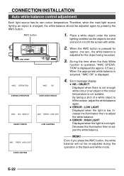
... balance is low. AWC OPERATION DURING OPERATION AWC NG : OBJECT OBJECT ERROR AWC OK DISPLAYING RESULT AWC ERROR : LOW LIGHT LOW LIGHTING 4. SET AWC MENU CAMERA SETUP EXT TERM-OFF INT/GL DUPLEX RX TERM-OFF NOT USED ON LL SIMPLEX ON IRIS VIDEO DC 2. Error message display ● NG : OBJECT...
... balance is low. AWC OPERATION DURING OPERATION AWC NG : OBJECT OBJECT ERROR AWC OK DISPLAYING RESULT AWC ERROR : LOW LIGHT LOW LIGHTING 4. SET AWC MENU CAMERA SETUP EXT TERM-OFF INT/GL DUPLEX RX TERM-OFF NOT USED ON LL SIMPLEX ON IRIS VIDEO DC 2. Error message display ● NG : OBJECT...

Instruction Manual
Page 23
... EAK SHUT T ER ( E x DR ) AGC MODE SENSE UP PR I OR I T Y BLC NORMAL 8: 2 NORMAL 2 0 dB OF F --- OF F If you wish to a desired item. OF F SET MENU CAMERA SETUP EXT TERM-OFF INT/GL DUPLEX RX TERM-OFF NOT USED ON LL SIMPLEX ON IRIS VIDEO DC 1. Set the cursor (>) to set values... to a desired sub-menu using the , button. F A C TORY SET T I T Y BLC NORMAL 8: 2 NORMAL 2 0 dB OF F --- MENU SETTING Setting the menu MENU button SET AWC MENU CAMERA SETUP SET button 4. A L C SET T I NGS I R I S LEVEL AV ERAGE : P EAK SHUT T ER ( E x DR ) AGC MODE SENSE UP PR I OR I NGS . . 3. E-23...
... EAK SHUT T ER ( E x DR ) AGC MODE SENSE UP PR I OR I T Y BLC NORMAL 8: 2 NORMAL 2 0 dB OF F --- OF F If you wish to a desired item. OF F SET MENU CAMERA SETUP EXT TERM-OFF INT/GL DUPLEX RX TERM-OFF NOT USED ON LL SIMPLEX ON IRIS VIDEO DC 1. Set the cursor (>) to set values... to a desired sub-menu using the , button. F A C TORY SET T I T Y BLC NORMAL 8: 2 NORMAL 2 0 dB OF F --- MENU SETTING Setting the menu MENU button SET AWC MENU CAMERA SETUP SET button 4. A L C SET T I NGS I R I S LEVEL AV ERAGE : P EAK SHUT T ER ( E x DR ) AGC MODE SENSE UP PR I OR I NGS . . 3. E-23...

