
117 page operator's manual for the GY-HD250U
Page 4
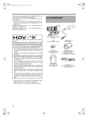
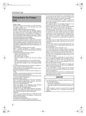
... To prevent electric shock, do NOT use cables not exceeding the following environments: z residential area (in the following length: Camera Port Cable DC IN Exclusive Cable VIDEO Coaxial Cable Y, PB, PR Coaxial Cable AUDIO INPUT1, INPUT2 Shielded Cable AUDIO OUT CH1, Shielded Cable CH2 Phones1, 2 ...of Japan Limited is on the bottom of the corresponding European Directives. NOTE: The rating plate (serial number plate) is : JVC Technology Centre Europe GmbH P.O. This unit should be placed close to qualified service personnel. The apparatus shall not be exposed to dripping...
... To prevent electric shock, do NOT use cables not exceeding the following environments: z residential area (in the following length: Camera Port Cable DC IN Exclusive Cable VIDEO Coaxial Cable Y, PB, PR Coaxial Cable AUDIO INPUT1, INPUT2 Shielded Cable AUDIO OUT CH1, Shielded Cable CH2 Phones1, 2 ...of Japan Limited is on the bottom of the corresponding European Directives. NOTE: The rating plate (serial number plate) is : JVC Technology Centre Europe GmbH P.O. This unit should be placed close to qualified service personnel. The apparatus shall not be exposed to dripping...
117 page operator's manual for the GY-HD250U
Page 6
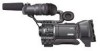
...• A lens is included with the GY-HD250CHU and GY- Marks such as ™, ® and © are trademarks or registered trademarks of copyright holders. • JVC cannot assume liabilities that both video and audio are recorded correctly. • Recorded video and audio contents are for U model) X ...records and plays back in this manual are not used . Other use . HD251CHE. These instructions are for purchasing the JVC GY-HD250U/CHU and GY-HD251E/CHE HD CAMERA RECORDER. ACCESSORIES / This device is not included with the GY-HD250U and GY-HD251E. • A lens is ...
...• A lens is included with the GY-HD250CHU and GY- Marks such as ™, ® and © are trademarks or registered trademarks of copyright holders. • JVC cannot assume liabilities that both video and audio are recorded correctly. • Recorded video and audio contents are for U model) X ...records and plays back in this manual are not used . Other use . HD251CHE. These instructions are for purchasing the JVC GY-HD250U/CHU and GY-HD251E/CHE HD CAMERA RECORDER. ACCESSORIES / This device is not included with the GY-HD250U and GY-HD251E. • A lens is ...
117 page operator's manual for the GY-HD250U
Page 7
... scan) HDV 1080i (1080 effective scan lines, interlaced scan) GY-HD250/GY-HD251 supports HDV 720p format. (HDV 720p) HDV and are two types of frames as you to switch camera settings instantly to other non-NTSC/PAL format screens. • Slow shutter Makes it records in...position even in back light conditions or when a bright subject moves in a frame. • Safety Zone indication in viewfinder • Zebra pattern video level indication in viewfinder • Full Auto Shooting (FAS) function Eliminates the need for highquality picture 1/3" 3-CCD with IEEE1394 connector, such as a...
... scan) HDV 1080i (1080 effective scan lines, interlaced scan) GY-HD250/GY-HD251 supports HDV 720p format. (HDV 720p) HDV and are two types of frames as you to switch camera settings instantly to other non-NTSC/PAL format screens. • Slow shutter Makes it records in...position even in back light conditions or when a bright subject moves in a frame. • Safety Zone indication in viewfinder • Zebra pattern video level indication in viewfinder • Full Auto Shooting (FAS) function Eliminates the need for highquality picture 1/3" 3-CCD with IEEE1394 connector, such as a...
117 page operator's manual for the GY-HD250U
Page 8
...Magnified Status Indications on the LCD Monitor. . . . . 29 Auto White Balance Indication (Camera mode only) . . . . 30 Menu Setting Screen 30 Alarm Message Display 30 Safety Zone Indication (Camera mode only 30 Switching between the LCD Screen and Viewfinder Display 31 PREPARATIONS Basic System 32 ...52 Full Auto White Balance (FAW 52 White Shading Adjustment 53 SETTING AND ADJUSTMENTS BEFORE SHOOTING Setting the Video Format 54 Setting the FRAME RATE Item 54 Camera Settings 55 Screen Size (4:3/16:9) Mode Selection 55 Audio Input Signal Selection 56 Selecting the CH-2 channel...
...Magnified Status Indications on the LCD Monitor. . . . . 29 Auto White Balance Indication (Camera mode only) . . . . 30 Menu Setting Screen 30 Alarm Message Display 30 Safety Zone Indication (Camera mode only 30 Switching between the LCD Screen and Viewfinder Display 31 PREPARATIONS Basic System 32 ...52 Full Auto White Balance (FAW 52 White Shading Adjustment 53 SETTING AND ADJUSTMENTS BEFORE SHOOTING Setting the Video Format 54 Setting the FRAME RATE Item 54 Camera Settings 55 Screen Size (4:3/16:9) Mode Selection 55 Audio Input Signal Selection 56 Selecting the CH-2 channel...
117 page operator's manual for the GY-HD250U
Page 9
...Resetting the menu settings to the factory settings . . . .102 Initializing (formatting) an SD memory card 102 FEATURES OF THE CAMERA SECTION How to Use Skin Detail 103 Outputting Color Bars 105 OTHERS Warnings and Responses 106 Troubleshooting 110 How to Display the Hour ...MENU SCREENS Menu Screen Configuration 73 Setting Menu Screens 75 TOP MENU Screen 76 VIDEO FORMAT[1/2] Menu Screen 77 VIDEO FORMAT[2/2] Menu Screen 79 CAMERA OPERATION Menu Screen 80 CAMERA PROCESS[1/2] Menu Screen 81 CAMERA PROCESS[2/2] Menu Screen 82 ADVANCED PROCESS Menu Screen 83 COLOR MATRIX ADJUST Menu...
...Resetting the menu settings to the factory settings . . . .102 Initializing (formatting) an SD memory card 102 FEATURES OF THE CAMERA SECTION How to Use Skin Detail 103 Outputting Color Bars 105 OTHERS Warnings and Responses 106 Troubleshooting 110 How to Display the Hour ...MENU SCREENS Menu Screen Configuration 73 Setting Menu Screens 75 TOP MENU Screen 76 VIDEO FORMAT[1/2] Menu Screen 77 VIDEO FORMAT[2/2] Menu Screen 79 CAMERA OPERATION Menu Screen 80 CAMERA PROCESS[1/2] Menu Screen 81 CAMERA PROCESS[2/2] Menu Screen 82 ADVANCED PROCESS Menu Screen 83 COLOR MATRIX ADJUST Menu...
117 page operator's manual for the GY-HD250U
Page 10
... transformers, motors, etc., or near devices emitting radio waves, such as transceivers or cellular phones. • Use of wireless microphone near the camera When a wireless microphone or wireless microphone tuner is used for a long period of the provided microphone is set the POWER switch to OFF in...device with water (especially when shooting in damage. If placed on the screen. This is not recorded on when you are not using the video/ audio signal output connectors. CAUTION • Do not point the lens or viewfinder directly at the sun or other than the reference input...
... transformers, motors, etc., or near devices emitting radio waves, such as transceivers or cellular phones. • Use of wireless microphone near the camera When a wireless microphone or wireless microphone tuner is used for a long period of the provided microphone is set the POWER switch to OFF in...device with water (especially when shooting in damage. If placed on the screen. This is not recorded on when you are not using the video/ audio signal output connectors. CAUTION • Do not point the lens or viewfinder directly at the sun or other than the reference input...

117 page operator's manual for the GY-HD250U
Page 13
...smear") when shooting an extremely bright light source. Do not leave the videocassette inserted when moving this device is placed in a Video tape very humid place. As far as condensation (dew). As condensation forms gradually, the condensation indication may remain in the ...increase. White dots High temperatures can cause CCD sensor pixels to be dissolved. • To prevent condensation When moving the camera under conditions where the temperature of the new environment before the condensation indication appears. eocassette, place this device is exposed directly...
...smear") when shooting an extremely bright light source. Do not leave the videocassette inserted when moving this device is placed in a Video tape very humid place. As far as condensation (dew). As condensation forms gradually, the condensation indication may remain in the ...increase. White dots High temperatures can cause CCD sensor pixels to be dissolved. • To prevent condensation When moving the camera under conditions where the temperature of the new environment before the condensation indication appears. eocassette, place this device is exposed directly...
117 page operator's manual for the GY-HD250U
Page 14
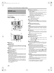
...speed. MEMO If the speed becomes too fast, hunting may occur. b[ZOOM] ZOOM mode knob S : Servo zoom mode. Secure with the GY-HD250CHU or the GY-HD251CHE. dMacro focusing ring (for telephoto shots. • Pushing harder changes the speed of the macro image, rotate this button ...ZOOM Lens The zoom lens is not provided with the screw knob after adjustment. When the camera control unit is connected, you can monitor the return video signal on the viewfinder, LCD monitor and video signal connector while this button as the FOCUS ASSIST button. X See "Back Focus Adjustment"...
...speed. MEMO If the speed becomes too fast, hunting may occur. b[ZOOM] ZOOM mode knob S : Servo zoom mode. Secure with the GY-HD250CHU or the GY-HD251CHE. dMacro focusing ring (for telephoto shots. • Pushing harder changes the speed of the macro image, rotate this button ...ZOOM Lens The zoom lens is not provided with the screw knob after adjustment. When the camera control unit is connected, you can monitor the return video signal on the viewfinder, LCD monitor and video signal connector while this button as the FOCUS ASSIST button. X See "Back Focus Adjustment"...
117 page operator's manual for the GY-HD250U
Page 19
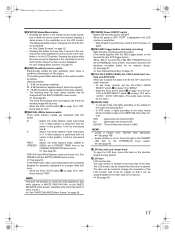
... the boosting level is performed with this switch. PRST : Switch into white balance mode memorized in the viewfinder or on the inner side of the camera. X See "Backup Recording" on page 19 is "ON", this button while the menu screen is located on the LCD monitor makes the menu... together with the SWITCH MODE menu screen. X See page 108. • Select whether or not to have this lights according to the setting for the video format being shot. • In VTR mode, it will be memorized into white balance mode memorized in PRESET TEMP. X See page 50. 15 X...
... the boosting level is performed with this switch. PRST : Switch into white balance mode memorized in the viewfinder or on the inner side of the camera. X See "Backup Recording" on page 19 is "ON", this button while the menu screen is located on the LCD monitor makes the menu... together with the SWITCH MODE menu screen. X See page 108. • Select whether or not to have this lights according to the setting for the video format being shot. • In VTR mode, it will be memorized into white balance mode memorized in PRESET TEMP. X See page 50. 15 X...
117 page operator's manual for the GY-HD250U
Page 20
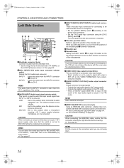
...(optional), a digital video component with setup in SET UP on the top section opens this terminal in VF SIGNAL on the LCD/VF[4/4] menu screen. MEMO You can select the normal input level for audio signals. • Outputs the input audio signal in the Camera mode. • Outputs...mode. e_hd250.book Page 16 Tuesday, October 24, 2006 3:11 PM CONTROLS, INDICATORS AND CONNECTORS Left Side Section 98 7 1 2 3 CH2-AUDIO OUT-CH1 VIDEO IEEE 1394 0 6 5 4 1Viewfinder connector (6-pin) Connect the cable from the viewfinder here. • Set the image format for connecting to an external ...
...(optional), a digital video component with setup in SET UP on the top section opens this terminal in VF SIGNAL on the LCD/VF[4/4] menu screen. MEMO You can select the normal input level for audio signals. • Outputs the input audio signal in the Camera mode. • Outputs...mode. e_hd250.book Page 16 Tuesday, October 24, 2006 3:11 PM CONTROLS, INDICATORS AND CONNECTORS Left Side Section 98 7 1 2 3 CH2-AUDIO OUT-CH1 VIDEO IEEE 1394 0 6 5 4 1Viewfinder connector (6-pin) Connect the cable from the viewfinder here. • Set the image format for connecting to an external ...
117 page operator's manual for the GY-HD250U
Page 21
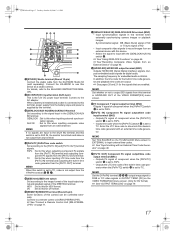
...the battery stops and power is not output from an external device. HDV : Set to AUX IN, the monitor turns black and video is supplied by this camera can be controlled externally. g[GENLOCK/AUX IN] GENLOCK/AUX IN terminal (BNC) • Input synchronization signals in time code generator ...not output from the [PR/TC OUT] terminal. Outputs embedded audio signals as a studio camera. j[PB/TC IN] Component PB signal output/time code input terminal (BNC) • Outputs PB signal of the VIDEO FORMAT[2/2] menu screen. Connect the KA-HD250 to use this switch is set to this terminal...
...the battery stops and power is not output from an external device. HDV : Set to AUX IN, the monitor turns black and video is supplied by this camera can be controlled externally. g[GENLOCK/AUX IN] GENLOCK/AUX IN terminal (BNC) • Input synchronization signals in time code generator ...not output from the [PR/TC OUT] terminal. Outputs embedded audio signals as a studio camera. j[PB/TC IN] Component PB signal output/time code input terminal (BNC) • Outputs PB signal of the VIDEO FORMAT[2/2] menu screen. Connect the KA-HD250 to use this switch is set to this terminal...
117 page operator's manual for the GY-HD250U
Page 23
.../DV signal from the IEEE1394 connector 0 on page 16, press the CAM/VTR button 5 on page 13 to turn on this automatically sets to camera video. • Auto iris mode operates even if the lens iris mode switch is used to select whether the mixed sound or stereo sound should be... on page 12. CH-1 : The CH-1 channel audio is output. CAUTION Make sure to move switches all of CH-1 is displayed on while the camera is in the FAS mode, it stops automatically. (Tape protect mode) During still picture playback and search mode, press this button during playback, still picture...
.../DV signal from the IEEE1394 connector 0 on page 16, press the CAM/VTR button 5 on page 13 to turn on this automatically sets to camera video. • Auto iris mode operates even if the lens iris mode switch is used to select whether the mixed sound or stereo sound should be... on page 12. CH-1 : The CH-1 channel audio is output. CAUTION Make sure to move switches all of CH-1 is displayed on while the camera is in the FAS mode, it stops automatically. (Tape protect mode) During still picture playback and search mode, press this button during playback, still picture...
117 page operator's manual for the GY-HD250U
Page 24
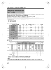
...) DV-24PA 480/60i(24p) E model only DV-50I DV-25P 576/50i 576/50i(25p) [1080I CAMERA] menu item Frame rate 60/30 ON 50/25 Rec on Tape q q q q q q q q q q Rec on the VIDEO FORMAT[2/2] menu screen) During recording and playback, image formats from external devices. Notes about the table (Shaded): ...480/60i q q q q q Composite Out 480/60i 576/50i „ In PLAY mode Playback IEEE 1394 Out NATIVE Component / SDI Out [HDV PB OUTPUT] menu item 720P 1080I NTSC HDV 720/60p 720/30p 720/50p 720/25p 720/24p q q q 1080/60i 480/60i q 720/60p q 1080/60i 480/60i q q q 1080/50i...
...) DV-24PA 480/60i(24p) E model only DV-50I DV-25P 576/50i 576/50i(25p) [1080I CAMERA] menu item Frame rate 60/30 ON 50/25 Rec on Tape q q q q q q q q q q Rec on the VIDEO FORMAT[2/2] menu screen) During recording and playback, image formats from external devices. Notes about the table (Shaded): ...480/60i q q q q q Composite Out 480/60i 576/50i „ In PLAY mode Playback IEEE 1394 Out NATIVE Component / SDI Out [HDV PB OUTPUT] menu item 720P 1080I NTSC HDV 720/60p 720/30p 720/50p 720/25p 720/24p q q q 1080/60i 480/60i q 720/60p q 1080/60i 480/60i q q q 1080/50i...

117 page operator's manual for the GY-HD250U
Page 26
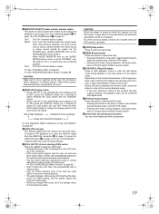
... also used for the VTR mode. • Each time the STATUS button is pressed in the Camera mode, one of 5 status screens is ON, characters are also shown on images from the Y/PB/PR OUT and VIDEO OUT terminals. on the OTHERS[1/2] menu screen is displayed. (STATUS 0, 1, 2, 3, 4) •... One type of the status screens. is displayed. The contents of the status display are divided into those for the Camera mode and those for the following character displays...
... also used for the VTR mode. • Each time the STATUS button is pressed in the Camera mode, one of 5 status screens is ON, characters are also shown on images from the Y/PB/PR OUT and VIDEO OUT terminals. on the OTHERS[1/2] menu screen is displayed. (STATUS 0, 1, 2, 3, 4) •... One type of the status screens. is displayed. The contents of the status display are divided into those for the Camera mode and those for the following character displays...
117 page operator's manual for the GY-HD250U
Page 28
... TO VTR MODE mode REC/VTR trigger button was pressed when 1080I REC INVALID 1080I CAMERA in the VIDEO FORMAT[1/2] menu screen was set to PRST (PRESET). *4 " ** " depends on the video format. X See page 86. *2 Displayed if functions were assigned to the DR-HD100 INSTRUCTION MANUAL.) a AUX ...is ON. LCD BRIGHT indication When the brightness of Black operation B : Displayed when the black stretch or black compress settings are set on the video format setting. ALC : Displayed when ALC function alone is ON. ation [: DR-HD100 is connected (displays white) [: Recording with the LCD ...
... TO VTR MODE mode REC/VTR trigger button was pressed when 1080I REC INVALID 1080I CAMERA in the VIDEO FORMAT[1/2] menu screen was set to PRST (PRESET). *4 " ** " depends on the video format. X See page 86. *2 Displayed if functions were assigned to the DR-HD100 INSTRUCTION MANUAL.) a AUX ...is ON. LCD BRIGHT indication When the brightness of Black operation B : Displayed when the black stretch or black compress settings are set on the video format setting. ALC : Displayed when ALC function alone is ON. ation [: DR-HD100 is connected (displays white) [: Recording with the LCD ...

117 page operator's manual for the GY-HD250U
Page 31
...A F symbol is selected) 0° to 360° STATUS 3 Displays a list of setting statuses for USER1, 2, and 3 as well as LENS RET item on the video format. For PRESET, 32 or 56. ON, OFF GAIN 0dB, 3dB, 6dB, 9dB, 12dB, 15dB, 18dB, ALC SHUTTER* (When STEP is selected) OFF, 1/6, 1/6.... menu screen. on page 42. 27 e_hd250.book Page 27 Tuesday, October 24, 2006 3:11 PM STATUS 2 Screen STATUS 2 This screen displays the camera setup statuses. STATUS 3 Screen Indication FILE FULL AUTO Indication Contents FILE F CAM1 CAM2-4 and EXT1 - 4 indicates SUB NAME X See pages 100-102...
...A F symbol is selected) 0° to 360° STATUS 3 Displays a list of setting statuses for USER1, 2, and 3 as well as LENS RET item on the video format. For PRESET, 32 or 56. ON, OFF GAIN 0dB, 3dB, 6dB, 9dB, 12dB, 15dB, 18dB, ALC SHUTTER* (When STEP is selected) OFF, 1/6, 1/6.... menu screen. on page 42. 27 e_hd250.book Page 27 Tuesday, October 24, 2006 3:11 PM STATUS 2 Screen STATUS 2 This screen displays the camera setup statuses. STATUS 3 Screen Indication FILE FULL AUTO Indication Contents FILE F CAM1 CAM2-4 and EXT1 - 4 indicates SUB NAME X See pages 100-102...

117 page operator's manual for the GY-HD250U
Page 34
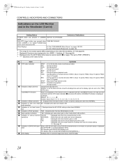
...24, 2006 3:11 PM CONTROLS, INDICATORS AND CONNECTORS Indications on the LCD Monitor and in the Viewfinder (Cont'd) Auto White Balance Indication (Camera mode only) The AUTO WHITE indication and the result of the following alarm messages are displayed during the auto white balance adjustment operation. In ...the VTR, a warning message with the SAFETY ZONE item and CENTER MARK item on the REC item setting and the ASPECT item setting in the VIDEO FORMAT menu screen, as shown below. SAFETY ZONE OFF 4:3 14:9 16:9 16:9+4:3 CENTER MARK - Alarm Message Display • The following ...
...24, 2006 3:11 PM CONTROLS, INDICATORS AND CONNECTORS Indications on the LCD Monitor and in the Viewfinder (Cont'd) Auto White Balance Indication (Camera mode only) The AUTO WHITE indication and the result of the following alarm messages are displayed during the auto white balance adjustment operation. In ...the VTR, a warning message with the SAFETY ZONE item and CENTER MARK item on the REC item setting and the ASPECT item setting in the VIDEO FORMAT menu screen, as shown below. SAFETY ZONE OFF 4:3 14:9 16:9 16:9+4:3 CENTER MARK - Alarm Message Display • The following ...

117 page operator's manual for the GY-HD250U
Page 40
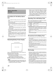
...-in the power source voltage, power sources generating noise, such as the AC power supply. 1. Clamp filter DC INPUT IEEE 1394 CH2-AUDIO OUT-CH1 VIDEO Charging the Built-in Battery The built-in battery 1. Power is discharged but it is possible to the VTR section and the...
...-in the power source voltage, power sources generating noise, such as the AC power supply. 1. Clamp filter DC INPUT IEEE 1394 CH2-AUDIO OUT-CH1 VIDEO Charging the Built-in Battery The built-in battery 1. Power is discharged but it is possible to the VTR section and the...
117 page operator's manual for the GY-HD250U
Page 42
... the values in the table on the above for approximate reference times. • Operating time is reduced in the Camera mode) • Alarm indication: LOW VOLTAGE displayed. „ FRONT and BACK TALLY lamp on the age of...Dionic 90 (U model) Approx. 3.2 hours Endura-7 (E model) Approx. 2.5 hours • Battery operating time may differ depending on camera: Blinks „ Monitoring loudspeaker and PHONES jack: Alarm sound MEMO • After the remaining battery power warnings appear, the GY-HD250... the battery pack capacity has been used up, set to the video and audio signals occurs.
... the values in the table on the above for approximate reference times. • Operating time is reduced in the Camera mode) • Alarm indication: LOW VOLTAGE displayed. „ FRONT and BACK TALLY lamp on the age of...Dionic 90 (U model) Approx. 3.2 hours Endura-7 (E model) Approx. 2.5 hours • Battery operating time may differ depending on camera: Blinks „ Monitoring loudspeaker and PHONES jack: Alarm sound MEMO • After the remaining battery power warnings appear, the GY-HD250... the battery pack capacity has been used up, set to the video and audio signals occurs.
117 page operator's manual for the GY-HD250U
Page 80
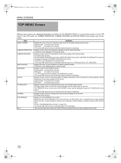
...of LCD monitor. Displays a menu screen for shooting and playing back video. Displays the menu screens related to display characters on the LCD monitor or in camera mode. VTR mode : It consists of two screens. Item VIDEO FORMAT.. Displays a menu screen for setting the operation mode for ...adjustments of the picture quality of the camera image. It consists of two screens. The ADVANCED PROCESS...
...of LCD monitor. Displays a menu screen for shooting and playing back video. Displays the menu screens related to display characters on the LCD monitor or in camera mode. VTR mode : It consists of two screens. Item VIDEO FORMAT.. Displays a menu screen for setting the operation mode for ...adjustments of the picture quality of the camera image. It consists of two screens. The ADVANCED PROCESS...


