117 page operator's manual for the GY-HD250U
Page 1
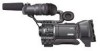
Retain this JVC product. Model No. For Customer Use: Enter below the Serial No. LST0440-001B e_hd250_cover_7.fm Page 1 Tuesday, October 24, 2006 3:13 PM © 2006 Victor Company of Japan, Limited GY-HD250/GY-HD251 HD CAMERA RECORDER HD CAMERA RECORDER GY-HD250 INSTRUCTIONS GY-HD251 E INTRODUCTION CONTROLS, INDICATORS AND CONNECTORS.... Before operating this device, please read the instructions carefully to ensure the best possible performance. Serial No. * The illustration shows the GY-HD250/GYHD251 HD CAMERA RECORDER with the provided lens, viewfinder and microphone attached.
Retain this JVC product. Model No. For Customer Use: Enter below the Serial No. LST0440-001B e_hd250_cover_7.fm Page 1 Tuesday, October 24, 2006 3:13 PM © 2006 Victor Company of Japan, Limited GY-HD250/GY-HD251 HD CAMERA RECORDER HD CAMERA RECORDER GY-HD250 INSTRUCTIONS GY-HD251 E INTRODUCTION CONTROLS, INDICATORS AND CONNECTORS.... Before operating this device, please read the instructions carefully to ensure the best possible performance. Serial No. * The illustration shows the GY-HD250/GYHD251 HD CAMERA RECORDER with the provided lens, viewfinder and microphone attached.
117 page operator's manual for the GY-HD250U
Page 6
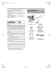
... rights of copyright holders. • JVC cannot assume liabilities that both video and audio are recorded correctly. • Recorded video and audio contents are trademarks or registered trademarks of this device or the videocassette. * All product names in the SP mode. Videocassettes marked with the GY-HD250CHU and GY- HD251CHE. ACCESSORIES / This device is...
... rights of copyright holders. • JVC cannot assume liabilities that both video and audio are recorded correctly. • Recorded video and audio contents are trademarks or registered trademarks of this device or the videocassette. * All product names in the SP mode. Videocassettes marked with the GY-HD250CHU and GY- HD251CHE. ACCESSORIES / This device is...
117 page operator's manual for the GY-HD250U
Page 7
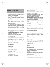
...enabled Records composite video signals from the video output connectors. HDV 720p (720 effective scan lines, progressive scan) HDV 1080i (1080 effective scan lines, interlaced scan) GY-HD250/GY-HD251 supports HDV 720p format. (HDV 720p) HDV and are two types of dark subjects with IEEE1394 ...• IEEE1394 connector IEEE1394 connector (6-pin) provided. e_hd250.book Page 3 Tuesday, October 24, 2006 3:11 PM MAIN FEATURES • GY-HD250/GY-HD251 records in a menu screen. • Cross-convert video output You can output converted video from an external source. • GENLOCK...
...enabled Records composite video signals from the video output connectors. HDV 720p (720 effective scan lines, progressive scan) HDV 1080i (1080 effective scan lines, interlaced scan) GY-HD250/GY-HD251 supports HDV 720p format. (HDV 720p) HDV and are two types of dark subjects with IEEE1394 ...• IEEE1394 connector IEEE1394 connector (6-pin) provided. e_hd250.book Page 3 Tuesday, October 24, 2006 3:11 PM MAIN FEATURES • GY-HD250/GY-HD251 records in a menu screen. • Cross-convert video output You can output converted video from an external source. • GENLOCK...
117 page operator's manual for the GY-HD250U
Page 11
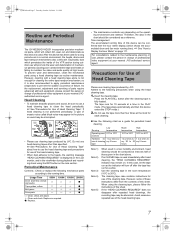
...transport mechanisms also collect dirt. Time management The accumulated running time of failure. For consultations related to use cleaning tape produced by JVC. Use the cleaning tape in the chart above. When using the cleaning tape, please follow the instructions of the VTR section ... If an M-DV80 tape is used. e_hd250.book Page 7 Tuesday, October 24, 2006 3:11 PM Routine and Periodical Maintenance The GY-HD250/GY-HD251 incorporates precision mechanical parts, which will collect dirt, wear out and deteriorate as this device is used immediately after head cleaning, the...
...transport mechanisms also collect dirt. Time management The accumulated running time of failure. For consultations related to use cleaning tape produced by JVC. Use the cleaning tape in the chart above. When using the cleaning tape, please follow the instructions of the VTR section ... If an M-DV80 tape is used. e_hd250.book Page 7 Tuesday, October 24, 2006 3:11 PM Routine and Periodical Maintenance The GY-HD250/GY-HD251 incorporates precision mechanical parts, which will collect dirt, wear out and deteriorate as this device is used immediately after head cleaning, the...

117 page operator's manual for the GY-HD250U
Page 12
... and do not store them lying flat. e_hd250.book Page 8 Tuesday, October 24, 2006 3:11 PM INTRODUCTION Battery Pack to be Used The GY-HD250/GY-HD251 can cause distortions and deformations of the tape edges. 8 Also it may damage the tape. Temperature Humidity Hourly temperature change Hourly humidity change...Long period (Over 10 years) 15°C to 23°C 15°C to 19°C 40% to 55% 25% to be Used • Use JVC's videocassette tapes marked with its tape not being overwritten. • To record on the way the HD camera recorder is recommended that you record and...
... and do not store them lying flat. e_hd250.book Page 8 Tuesday, October 24, 2006 3:11 PM INTRODUCTION Battery Pack to be Used The GY-HD250/GY-HD251 can cause distortions and deformations of the tape edges. 8 Also it may damage the tape. Temperature Humidity Hourly temperature change Hourly humidity change...Long period (Over 10 years) 15°C to 23°C 15°C to 19°C 40% to 55% 25% to be Used • Use JVC's videocassette tapes marked with its tape not being overwritten. • To record on the way the HD camera recorder is recommended that you record and...
117 page operator's manual for the GY-HD250U
Page 14
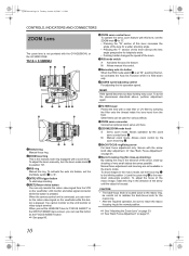
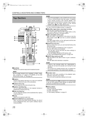
... filters can use this button is located close -up shooting of the arrow until the object is the manual zoom ring equipped with the GY-HD250CHU or the GY-HD251CHE. aZOOM servo connector Connect an optional zoom servo unit here. Allows zoom control by the zoom servo control lever 6. Secure with a clear filter...
... filters can use this button is located close -up shooting of the arrow until the object is the manual zoom ring equipped with the GY-HD250CHU or the GY-HD251CHE. aZOOM servo connector Connect an optional zoom servo unit here. Allows zoom control by the zoom servo control lever 6. Secure with a clear filter...
117 page operator's manual for the GY-HD250U
Page 15
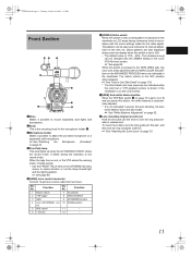
... for manual adjustment of the lens iris. X See "Attaching the Zoom Lens" on page 33. 4Front tally lamp This lamp lights up when the GY-HD250/GY-HD251 enters the record mode. While this button, the white balance is automatically adjusted. * It is not activated in the viewfinder or on the LCD...
... for manual adjustment of the lens iris. X See "Attaching the Zoom Lens" on page 33. 4Front tally lamp This lamp lights up when the GY-HD250/GY-HD251 enters the record mode. While this button, the white balance is automatically adjusted. * It is not activated in the viewfinder or on the LCD...
117 page operator's manual for the GY-HD250U
Page 16
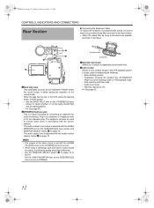
... • When using a stereotype jack and stereo sound should be output, the following : • Menu Setting screens • Characters showing the whether the GY-HD250/GYHD251 is set with the ALARM VR LEVEL item on the OTHERS[1/2] menu screen to select whether or not the lamp should be output... d on the AUDIO/MIC[2/2] menu screen to STEREO. Plug in the figure. 1 2 3 4 1Back tally lamp This lamp lights up when the GY-HD250/GY-HD251 enters the record mode. MEMO • The volume of unwanted radio waves, be used for audio monitoring. Earphone cable Clamp filter 3Shoulder belt hooks...
... • When using a stereotype jack and stereo sound should be output, the following : • Menu Setting screens • Characters showing the whether the GY-HD250/GYHD251 is set with the ALARM VR LEVEL item on the OTHERS[1/2] menu screen to select whether or not the lamp should be output... d on the AUDIO/MIC[2/2] menu screen to STEREO. Plug in the figure. 1 2 3 4 1Back tally lamp This lamp lights up when the GY-HD250/GY-HD251 enters the record mode. MEMO • The volume of unwanted radio waves, be used for audio monitoring. Earphone cable Clamp filter 3Shoulder belt hooks...
117 page operator's manual for the GY-HD250U
Page 22
Use this to prevent unwanted recording. (The REC trigger button on GY-HD250/GY-HD251. • You can insert and remove the SD memory card. X See "FILE MANAGE Menu Screen" on page 37. MEMO • It takes a few seconds ...
Use this to prevent unwanted recording. (The REC trigger button on GY-HD250/GY-HD251. • You can insert and remove the SD memory card. X See "FILE MANAGE Menu Screen" on page 37. MEMO • It takes a few seconds ...

117 page operator's manual for the GY-HD250U
Page 36
...Cable RCA pin Audio Cable RCA pin 1/3 Zoom Lens Th13 × 3.5BRMU (FUJINON) Microphone GY-HD250/GY-HD251 IEEE1394 Cable 6P-6P For GY-HD250 Wide Converter WCV-82SC Focus Manual Unit *1 Zoom Servo Unit HZ-ZS13B 1/3 Zoom Lens ...LEVEL CH-2 ON OFF POWER REC SD Memory Card Battery mount GY-HD250: Gold Mount GY-HD251: V Mount Anton Bauer Battery Anton Bauer Battery Charger For GY-HD251 GY-HD250/GY-HD251 Standard Package Mount Converter (1/2r1/3): ACM-12 (2/3r1/3): ACM...a FUJINON focus manual unit (FMM-8, CFH-3, CFC-12-990). For details, please consult your JVC authorized dealer.
...Cable RCA pin Audio Cable RCA pin 1/3 Zoom Lens Th13 × 3.5BRMU (FUJINON) Microphone GY-HD250/GY-HD251 IEEE1394 Cable 6P-6P For GY-HD250 Wide Converter WCV-82SC Focus Manual Unit *1 Zoom Servo Unit HZ-ZS13B 1/3 Zoom Lens ...LEVEL CH-2 ON OFF POWER REC SD Memory Card Battery mount GY-HD250: Gold Mount GY-HD251: V Mount Anton Bauer Battery Anton Bauer Battery Charger For GY-HD251 GY-HD250/GY-HD251 Standard Package Mount Converter (1/2r1/3): ACM-12 (2/3r1/3): ACM...a FUJINON focus manual unit (FMM-8, CFH-3, CFC-12-990). For details, please consult your JVC authorized dealer.

117 page operator's manual for the GY-HD250U
Page 37
... connector How to secure the microphone. 4. Incomplete tightening may result in the lens dropping off or disturbed back focus. • Set the GY-HD250/GY-HD251's power switch to loosen it from interfering with the hole in the direction of the arrow. 2. Turn the knob on the microphone holder...book Page 33 Tuesday, October 24, 2006 3:11 PM Attaching the Zoom Lens 1. 3. Connect the cable connector. 5. Turn the knob on the GY-HD250/GY-HD251. 5. Attach the microphone cable to the INPUT1 or INPUT2 input connector on the microphone holder anticlockwise to "OFF" before the zoom lens is...
... connector How to secure the microphone. 4. Incomplete tightening may result in the lens dropping off or disturbed back focus. • Set the GY-HD250/GY-HD251's power switch to loosen it from interfering with the hole in the direction of the arrow. 2. Turn the knob on the microphone holder...book Page 33 Tuesday, October 24, 2006 3:11 PM Attaching the Zoom Lens 1. 3. Connect the cable connector. 5. Turn the knob on the GY-HD250/GY-HD251. 5. Attach the microphone cable to the INPUT1 or INPUT2 input connector on the microphone holder anticlockwise to "OFF" before the zoom lens is...

117 page operator's manual for the GY-HD250U
Page 38
... comes out slightly. 2. Cutout 34 SD memory card cover sible, as close to the "LOCK" position. X See "FILE MANAGE Menu Screen" on GY-HD250/GY-HD251. Open the SD memory card cover. 2. Pull the SD memory card straight out. Set the switch on page 14. Recommended SD memory cards Panasonic...PREPARATIONS About the Viewfinder Cable Attach the viewfinder cable to 2 GB • You can save and call up menu settings and camera settings for GY-HD250/GY-HD251. Taking out the SD memory card 1. To reduce the emission of unwanted radio waves, be used with this device as shown in ...
... comes out slightly. 2. Cutout 34 SD memory card cover sible, as close to the "LOCK" position. X See "FILE MANAGE Menu Screen" on GY-HD250/GY-HD251. Open the SD memory card cover. 2. Pull the SD memory card straight out. Set the switch on page 14. Recommended SD memory cards Panasonic...PREPARATIONS About the Viewfinder Cable Attach the viewfinder cable to 2 GB • You can save and call up menu settings and camera settings for GY-HD250/GY-HD251. Taking out the SD memory card 1. To reduce the emission of unwanted radio waves, be used with this device as shown in ...

117 page operator's manual for the GY-HD250U
Page 40
... amount of unnecessary radio waves emitted, attach a provided Clamp filter near both ends of the positions). 3. However, it gradually discharges while the GY-HD250/GY-HD251 is being charged for about three months, in which case the set the date and time and time code data again. DC cable DC...about 4 hours. • The built-in the diagram. e_hd250.book Page 36 Tuesday, October 24, 2006 3:11 PM PREPARATIONS AC Operation The GY-HD250/GY-HD251 is supplied to the VTR section and the camera. Use the AC adapter as shown in battery will be recorded. The built-in battery...
... amount of unnecessary radio waves emitted, attach a provided Clamp filter near both ends of the positions). 3. However, it gradually discharges while the GY-HD250/GY-HD251 is being charged for about three months, in which case the set the date and time and time code data again. DC cable DC...about 4 hours. • The built-in the diagram. e_hd250.book Page 36 Tuesday, October 24, 2006 3:11 PM PREPARATIONS AC Operation The GY-HD250/GY-HD251 is supplied to the VTR section and the camera. Use the AC adapter as shown in battery will be recorded. The built-in battery...

117 page operator's manual for the GY-HD250U
Page 41
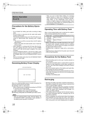
..., October 24, 2006 3:11 PM Battery Operation The attachable battery varies depending on the way the HD camera recorder is used. „GY-HD250U Use an Anton Bauer battery. „GY-HD251E Use an IDX (Endura) battery. V-mount attachment V-mount Attaching the Battery 1. Release button Battery Battery pack (trim pack) LCD screen...
..., October 24, 2006 3:11 PM Battery Operation The attachable battery varies depending on the way the HD camera recorder is used. „GY-HD250U Use an Anton Bauer battery. „GY-HD251E Use an IDX (Endura) battery. V-mount attachment V-mount Attaching the Battery 1. Release button Battery Battery pack (trim pack) LCD screen...
117 page operator's manual for the GY-HD250U
Page 42
...camera: Blinks „ Monitoring loudspeaker and PHONES jack: Alarm sound MEMO • After the remaining battery power warnings appear, the GY-HD250/GY-HD251 automatically stops operation if the battery power operation is continued. 38 Recharging • Recharge the battery pack after completely discharging ...a small amount of the battery pack, charging conditions and the operating environment, etc. Then switch ON again. • If the GY-HD250/GY-HD251 is left with Battery Pack When a fully charged battery pack is attached, the approximate continuous operating time is as follows Battery...
...camera: Blinks „ Monitoring loudspeaker and PHONES jack: Alarm sound MEMO • After the remaining battery power warnings appear, the GY-HD250/GY-HD251 automatically stops operation if the battery power operation is continued. 38 Recharging • Recharge the battery pack after completely discharging ...a small amount of the battery pack, charging conditions and the operating environment, etc. Then switch ON again. • If the GY-HD250/GY-HD251 is left with Battery Pack When a fully charged battery pack is attached, the approximate continuous operating time is as follows Battery...

117 page operator's manual for the GY-HD250U
Page 43
... in the VTR operation mode indication area before the power is switched, the VTR indicator displays the following statuses. "STBY" is loaded, the GY-HD250/GY-HD251 enters the record-standby mode automatically. Remove the battery pack or the power supply to the DC INPUT connector. (When the camera is...CAM/VTR AUDIO SELECT CH-1 CH-2 AUTO MANU TC DISPLAY TC UB GENE. FREE REC REGEN POWER switch CAM/VTR button Camera mode The GY-HD250/GY-HD251 enters the Camera mode. The camera image will not be set to OFF before turning the power on in the viewfinder. The camera image...
... in the VTR operation mode indication area before the power is switched, the VTR indicator displays the following statuses. "STBY" is loaded, the GY-HD250/GY-HD251 enters the record-standby mode automatically. Remove the battery pack or the power supply to the DC INPUT connector. (When the camera is...CAM/VTR AUDIO SELECT CH-1 CH-2 AUTO MANU TC DISPLAY TC UB GENE. FREE REC REGEN POWER switch CAM/VTR button Camera mode The GY-HD250/GY-HD251 enters the Camera mode. The camera image will not be set to OFF before turning the power on in the viewfinder. The camera image...
117 page operator's manual for the GY-HD250U
Page 47
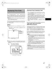
e_hd250.book Page 43 Tuesday, October 24, 2006 3:11 PM Displaying Time Code The GY-HD250/GY-HD251 records SMPTE-standard (NTSC) or EBU-standard (PAL) time codes and user's bits. The time codes or user's bits can be shown on the ...
e_hd250.book Page 43 Tuesday, October 24, 2006 3:11 PM Displaying Time Code The GY-HD250/GY-HD251 records SMPTE-standard (NTSC) or EBU-standard (PAL) time codes and user's bits. The time codes or user's bits can be shown on the ...

117 page operator's manual for the GY-HD250U
Page 51
... EXT TC mode „ VTR mode/IEEE1394 input mode TC/UB/CLOCK menu TC GENE. switch TCG SOURCE item TC DUPLI. item on Tape The GY-HD250/GY-HD251 also incorporates a time code reader. MEMO • During playback, if a portion of Time Codes Recorded on the TC/UB/CLOCK menu screen to...
... EXT TC mode „ VTR mode/IEEE1394 input mode TC/UB/CLOCK menu TC GENE. switch TCG SOURCE item TC DUPLI. item on Tape The GY-HD250/GY-HD251 also incorporates a time code reader. MEMO • During playback, if a portion of Time Codes Recorded on the TC/UB/CLOCK menu screen to...

117 page operator's manual for the GY-HD250U
Page 52
...2006 3:11 PM PREPARATIONS FOR OPERATION Synchronizing with the Time Code of the IEEE1394 (DV)-Connected Master Unit You can use the GY-HD250U, GY-HD251E, GY-HD110U, or GY-HD111E as a slave unit. IEEE1394 terminal IEEE1394 cable VF BRIGHT USER 1 USER 2 USER 3 ND FILTER 2 1 MENU... master unit and the slave unit with an IEEE1394 cable. Settings and Operations • Master unit (GY-HD100U/GY-HD100E/GY-HD101E/GYHD110U/GY-HD110E/GY-HD111E/GY-HD250U/GYHD251E) 1. Set to INTERNAL. (GY-HD250U, GY-HD251E) 5. Set TCG SOURCE in DV format and is then switched to [DV]. 2. Synchronize DROP...
...2006 3:11 PM PREPARATIONS FOR OPERATION Synchronizing with the Time Code of the IEEE1394 (DV)-Connected Master Unit You can use the GY-HD250U, GY-HD251E, GY-HD110U, or GY-HD111E as a slave unit. IEEE1394 terminal IEEE1394 cable VF BRIGHT USER 1 USER 2 USER 3 ND FILTER 2 1 MENU... master unit and the slave unit with an IEEE1394 cable. Settings and Operations • Master unit (GY-HD100U/GY-HD100E/GY-HD101E/GYHD110U/GY-HD110E/GY-HD111E/GY-HD250U/GYHD251E) 1. Set to INTERNAL. (GY-HD250U, GY-HD251E) 5. Set TCG SOURCE in DV format and is then switched to [DV]. 2. Synchronize DROP...

117 page operator's manual for the GY-HD250U
Page 60
... the audio input level control corresponding to the audio input level to be input to the INPUT1 or INPUT2 connector using a dynamic microphone. The GY-HD250/GY-HD251 is provided with the INPUT1 connector and the INPUT2 connector for each audio channel, use the CH-1/CH-2 AUDIO SELECT switch to select whether... 56 Tuesday, October 24, 2006 3:11 PM SETTING AND ADJUSTMENTS BEFORE SHOOTING Audio Input Signal Selection MEMO You can be adjusted manually when the GYHD250/GY-HD251 is in CH-2. STATUS 1 screen Audio level Indicator level (reference)
... the audio input level control corresponding to the audio input level to be input to the INPUT1 or INPUT2 connector using a dynamic microphone. The GY-HD250/GY-HD251 is provided with the INPUT1 connector and the INPUT2 connector for each audio channel, use the CH-1/CH-2 AUDIO SELECT switch to select whether... 56 Tuesday, October 24, 2006 3:11 PM SETTING AND ADJUSTMENTS BEFORE SHOOTING Audio Input Signal Selection MEMO You can be adjusted manually when the GYHD250/GY-HD251 is in CH-2. STATUS 1 screen Audio level Indicator level (reference)


