
Blu-ray disc distribution with ProHD
Page 1
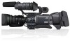
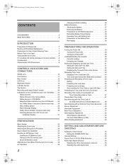
HD content distribution workflow FCP editing/Toast9 BD authoring by PowerMac G5 Acquisition Post Production Distribution GY-HD250 GY-HD200 HDV tape Edit:Final Cut Pro Version6.0.2 Authoring:Roxio Toast9 Titanium IEEE +Plug-in BR-HD50 1394 (AV/C) DR-HD100 Portable Monitor... USB2.0 BD drive Lacie d2 BDMV DT-V24L1U DT-V20L1U HDMI BD player 1 Blu-ray disc distribution with ProHD Thanks to FCP ver6.0.2 (NLE) and Toast 9 Titanium (Authoring software) with BD Recorder drive, We can offer complete HD contents distribution workflow with Blu-ray Disc (BDMV format), from 720p/1080i ...
HD content distribution workflow FCP editing/Toast9 BD authoring by PowerMac G5 Acquisition Post Production Distribution GY-HD250 GY-HD200 HDV tape Edit:Final Cut Pro Version6.0.2 Authoring:Roxio Toast9 Titanium IEEE +Plug-in BR-HD50 1394 (AV/C) DR-HD100 Portable Monitor... USB2.0 BD drive Lacie d2 BDMV DT-V24L1U DT-V20L1U HDMI BD player 1 Blu-ray disc distribution with ProHD Thanks to FCP ver6.0.2 (NLE) and Toast 9 Titanium (Authoring software) with BD Recorder drive, We can offer complete HD contents distribution workflow with Blu-ray Disc (BDMV format), from 720p/1080i ...
117 page operator's manual for the GY-HD250U
Page 1
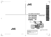
.../GY-HD251 HD CAMERA RECORDER HD CAMERA RECORDER GY-HD250 INSTRUCTIONS GY-HD251 E INTRODUCTION CONTROLS, INDICATORS AND CONNECTORS PREPARATIONS PREPARATIONS FOR OPERATION SETTING AND ADJUSTMENTS BEFORE SHOOTING SHOOTING OPERATION PLAYBACK MODE USING EXTERNAL COMPONENTS MENU SCREENS FEATURES OF THE CAMERA SECTION OTHERS LST0440-001B Thank you for purchasing this information for future reference. Retain this JVC...
.../GY-HD251 HD CAMERA RECORDER HD CAMERA RECORDER GY-HD250 INSTRUCTIONS GY-HD251 E INTRODUCTION CONTROLS, INDICATORS AND CONNECTORS PREPARATIONS PREPARATIONS FOR OPERATION SETTING AND ADJUSTMENTS BEFORE SHOOTING SHOOTING OPERATION PLAYBACK MODE USING EXTERNAL COMPONENTS MENU SCREENS FEATURES OF THE CAMERA SECTION OTHERS LST0440-001B Thank you for purchasing this information for future reference. Retain this JVC...
117 page operator's manual for the GY-HD250U
Page 6
... are for U model) X See page 35 2 Information applicable only to the GY-HD250U/CHU is marked by "(U model only)". These instructions are for purchasing the JVC GY-HD250U/CHU and GY-HD251E/CHE HD CAMERA RECORDER. Information applicable only to tracking errors. • This device records and plays back in this device may appear disturbed. • Digital noise...
... are for U model) X See page 35 2 Information applicable only to the GY-HD250U/CHU is marked by "(U model only)". These instructions are for purchasing the JVC GY-HD250U/CHU and GY-HD251E/CHE HD CAMERA RECORDER. Information applicable only to tracking errors. • This device records and plays back in this device may appear disturbed. • Digital noise...
117 page operator's manual for the GY-HD250U
Page 7
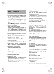
...signals from the video output connectors. e_hd250.book Page 3 Tuesday, October 24, 2006 3:11 PM MAIN FEATURES • GY-HD250/GY-HD251 records in viewfinder • Full Auto Shooting (FAS) function Eliminates the need for troublesome switch or filter operations by connecting ...Mini DV videocassettes. SC phase and HD/SD H phase adjustments can select this device. • Recording check function for convenient recording review function • Camera section designed with 3-CCD system for audio checking The input audio can output converted video from an external source. • ...
...signals from the video output connectors. e_hd250.book Page 3 Tuesday, October 24, 2006 3:11 PM MAIN FEATURES • GY-HD250/GY-HD251 records in viewfinder • Full Auto Shooting (FAS) function Eliminates the need for troublesome switch or filter operations by connecting ...Mini DV videocassettes. SC phase and HD/SD H phase adjustments can select this device. • Recording check function for convenient recording review function • Camera section designed with 3-CCD system for audio checking The input audio can output converted video from an external source. • ...
117 page operator's manual for the GY-HD250U
Page 8
... for Use of Head Cleaning Tape 7 Battery Pack to be Used 8 Videocassette to be Used 8 For recording and storing videotapes in the best condition . . . 8 Condensation 9 Characteristic CCD Phenomena 9 CONTROLS, INDICATORS AND CONNECTORS ZOOM Lens 10 Front Section 11 Rear Section 12 LCD Door 13 Right... Side Section 14 Left Side Section 16 Top Section 18 Recording and Image Output Formats 20 Indications on the LCD ...
... for Use of Head Cleaning Tape 7 Battery Pack to be Used 8 Videocassette to be Used 8 For recording and storing videotapes in the best condition . . . 8 Condensation 9 Characteristic CCD Phenomena 9 CONTROLS, INDICATORS AND CONNECTORS ZOOM Lens 10 Front Section 11 Rear Section 12 LCD Door 13 Right... Side Section 14 Left Side Section 16 Top Section 18 Recording and Image Output Formats 20 Indications on the LCD ...
117 page operator's manual for the GY-HD250U
Page 9
...5 Tuesday, October 24, 2006 3:11 PM Adjusting Audio during Recording 56 Monitoring Audio during Recording 57 SHOOTING OPERATION Basic Recording Operation 58 If the Record-Standby Mode Continues 59 Checking Recorded Contents in Record-Standby Mode (Recording Check Function 59 HEADER REC Function 60 PLAYBACK MODE Playback Procedure 62... Outputting Audio 63 USING EXTERNAL COMPONENTS Connecting the Video Signal Cables 64 Connecting the IEEE1394 Cable 64 Recording Composite Video Signals from an External Device 65 Using GENLOCK Functions 66 Dubbing with AV Devices 67 HDV/DV Dubbing ...
...5 Tuesday, October 24, 2006 3:11 PM Adjusting Audio during Recording 56 Monitoring Audio during Recording 57 SHOOTING OPERATION Basic Recording Operation 58 If the Record-Standby Mode Continues 59 Checking Recorded Contents in Record-Standby Mode (Recording Check Function 59 HEADER REC Function 60 PLAYBACK MODE Playback Procedure 62... Outputting Audio 63 USING EXTERNAL COMPONENTS Connecting the Video Signal Cables 64 Connecting the IEEE1394 Cable 64 Recording Composite Video Signals from an External Device 65 Using GENLOCK Functions 66 Dubbing with AV Devices 67 HDV/DV Dubbing ...
117 page operator's manual for the GY-HD250U
Page 10
...and the viewfinder screen, or red, blue, green and/or white spots may appear on a beach. Depending on the screen, but the impact on the CCD elements could result. • If the lens or viewfinder is not a camera malfunction. • Noise may be damaged. • The sensitivity level ...8226; Vibrations Colors may be incorrect if the camera is used near a radio or television transmitting antenna, in places where strong magnetic fields are not recorded on the tape. • If you use this is used for a long period of time, the characters displayed in head cleaner that the power...
...and the viewfinder screen, or red, blue, green and/or white spots may appear on a beach. Depending on the screen, but the impact on the CCD elements could result. • If the lens or viewfinder is not a camera malfunction. • Noise may be damaged. • The sensitivity level ...8226; Vibrations Colors may be incorrect if the camera is used near a radio or television transmitting antenna, in places where strong magnetic fields are not recorded on the tape. • If you use this is used for a long period of time, the characters displayed in head cleaner that the power...
117 page operator's manual for the GY-HD250U
Page 11
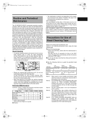
...See "How to 35°C). For consultations related to 2 times ev- Press the PLAY/STILL button after repeated head cleanings, the recording tape may be considered as required. indicator may be confirmed with a head cleaning tape alone is not enough for cleaning the entire ... use a head cleaning tape to prevent the sudden occurrence of mechanical parts by JVC. e_hd250.book Page 7 Tuesday, October 24, 2006 3:11 PM Routine and Periodical Maintenance The GY-HD250/GY-HD251 incorporates precision mechanical parts, which will collect dirt, wear out and deteriorate as...
...See "How to 35°C). For consultations related to 2 times ev- Press the PLAY/STILL button after repeated head cleanings, the recording tape may be considered as required. indicator may be confirmed with a head cleaning tape alone is not enough for cleaning the entire ... use a head cleaning tape to prevent the sudden occurrence of mechanical parts by JVC. e_hd250.book Page 7 Tuesday, October 24, 2006 3:11 PM Routine and Periodical Maintenance The GY-HD250/GY-HD251 incorporates precision mechanical parts, which will collect dirt, wear out and deteriorate as...

117 page operator's manual for the GY-HD250U
Page 12
...record...switch to SAVE to protect the required recording in the tape from being com- When...full performance due to be Used • Use JVC's videocassette tapes marked with the A symbol. &#...recorder is used . Temperature Humidity Hourly temperature change Hourly humidity change Recording ... Do not leave the videotapes neglected for the best recording and storage of videotapes. • Take care of...recommended batteries. pletely wound, as blocking). Switch For recording and storing videotapes in distortion of the tape edges....being overwritten. • To record on the tape, slide the switch...
...record...switch to SAVE to protect the required recording in the tape from being com- When...full performance due to be Used • Use JVC's videocassette tapes marked with the A symbol. &#...recorder is used . Temperature Humidity Hourly temperature change Hourly humidity change Recording ... Do not leave the videotapes neglected for the best recording and storage of videotapes. • Take care of...recommended batteries. pletely wound, as blocking). Switch For recording and storing videotapes in distortion of the tape edges....being overwritten. • To record on the tape, slide the switch...
117 page operator's manual for the GY-HD250U
Page 15
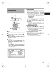
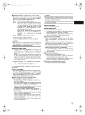
... Microphone (Provided)" on page 33. 11 X See "Attaching the Zoom Lens" on page 33. 4Front tally lamp This lamp lights up when the GY-HD250/GY-HD251 enters the record mode. Function 1 Return switch 7 Iris position 2 VTR trigger 8 IRIS A/R INPUT 3 GND 9 EXTENDER position 4 Lens AUTO/MANU con- 10 ZOOM position trol 5 IRIS control... until firm. The luminance level can be changed with the menu settings made for manual adjustment of the lens iris. The switch returns to the record mode.
... Microphone (Provided)" on page 33. 11 X See "Attaching the Zoom Lens" on page 33. 4Front tally lamp This lamp lights up when the GY-HD250/GY-HD251 enters the record mode. Function 1 Return switch 7 Iris position 2 VTR trigger 8 IRIS A/R INPUT 3 GND 9 EXTENDER position 4 Lens AUTO/MANU con- 10 ZOOM position trol 5 IRIS control... until firm. The luminance level can be changed with the menu settings made for manual adjustment of the lens iris. The switch returns to the record mode.
117 page operator's manual for the GY-HD250U
Page 16
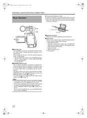
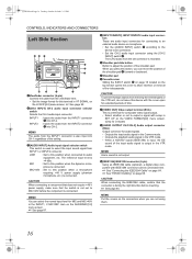
...menu screen to this device as possible, as shown in the figure. 1 2 3 4 1Back tally lamp This lamp lights up when the GY-HD250/GY-HD251 enters the record mode. MEMO • The volume of unwanted radio waves, be output, the following : • Menu Setting screens • Characters showing the... whether the GY-HD250/GYHD251 is set with the ALARM VR LEVEL item on the OTHERS[1/2] menu screen. • When using a stereotype jack...
...menu screen to this device as possible, as shown in the figure. 1 2 3 4 1Back tally lamp This lamp lights up when the GY-HD250/GY-HD251 enters the record mode. MEMO • The volume of unwanted radio waves, be output, the following : • Menu Setting screens • Characters showing the... whether the GY-HD250/GYHD251 is set with the ALARM VR LEVEL item on the OTHERS[1/2] menu screen. • When using a stereotype jack...
117 page operator's manual for the GY-HD250U
Page 17
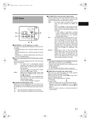
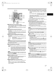
...switches between scenes. : The preset mode is being switched : Flashing In VTR mode : Lit In camera mode : Off • Select the Camera mode to record the camera image. • Select the VTR mode to playback VTR or to the input level. The "AUTO" LED in the viewfinder. (This switch works... of adjusting the CH-1 and CH-2 audio channel audio levels. The time code operates in the run mode. If this setting is used when recording scenes one after another , the time codes become discontinuous at the transition points between camera mode and VTR mode. While the mode is selected, ...
...switches between scenes. : The preset mode is being switched : Flashing In VTR mode : Lit In camera mode : Off • Select the Camera mode to record the camera image. • Select the VTR mode to playback VTR or to the input level. The "AUTO" LED in the viewfinder. (This switch works... of adjusting the CH-1 and CH-2 audio channel audio levels. The time code operates in the run mode. If this setting is used when recording scenes one after another , the time codes become discontinuous at the transition points between camera mode and VTR mode. While the mode is selected, ...
117 page operator's manual for the GY-HD250U
Page 19
...mode, video color temperatures are selectable with the switch in this button becomes the start /stop recording) Start and stop recording button for the video format being recorded on the LCD monitor. X See "Backup Recording" on page 75. f[CH-1/CH-2 AUDIO LEVEL] CH-1/CH-2 Audio level con- The ...performed with this knob on page 85. When the power is OFF, "POFF" is displayed in A. e[REC] REC trigger button (start /stop recording using this button. (This works together with the switch in this light in PRESET TEMP. X See page 86. HDV : Lights when the format...
...mode, video color temperatures are selectable with the switch in this button becomes the start /stop recording) Start and stop recording button for the video format being recorded on the LCD monitor. X See "Backup Recording" on page 75. f[CH-1/CH-2 AUDIO LEVEL] CH-1/CH-2 Audio level con- The ...performed with this knob on page 85. When the power is OFF, "POFF" is displayed in A. e[REC] REC trigger button (start /stop recording using this button. (This works together with the switch in this light in PRESET TEMP. X See page 86. HDV : Lights when the format...
117 page operator's manual for the GY-HD250U
Page 20
.... X See "HDV/DV Dubbing" on the AUDIO/MIC[1/2] menu screen. CAUTION When connecting the IEEE1394 cable, confirm that the switch is not set connector is recorded. 5Shoulder pad slide button Button to this device with IEEE1394 connector can move the position of the videocassette. The reference input level is connected. MIC...
.... X See "HDV/DV Dubbing" on the AUDIO/MIC[1/2] menu screen. CAUTION When connecting the IEEE1394 cable, confirm that the switch is not set connector is recorded. 5Shoulder pad slide button Button to this device with IEEE1394 connector can move the position of the videocassette. The reference input level is connected. MIC...
117 page operator's manual for the GY-HD250U
Page 21
... of the input/output signal and playback signal of this for the built-in time code generator when the [PBPR/TC] switch d is set to record images from an external device with the [GENLOCK/AUX IN] switch c. i[Y] Component Y signal output terminal (BNC) Outputs Y signal of the VIDEO FORMAT...and outputting the built-in OUTPUT TERM. [DV] on the VIDEO FORMAT[2/2] menu screen. (Only for the signals that are output. X See "Recording Composite Video Signals from any terminal. The sampling frequency for DV format. Connect the KA-HD250 to this device as digital audio. b[DC INPUT] DC...
... of the input/output signal and playback signal of this for the built-in time code generator when the [PBPR/TC] switch d is set to record images from an external device with the [GENLOCK/AUX IN] switch c. i[Y] Component Y signal output terminal (BNC) Outputs Y signal of the VIDEO FORMAT...and outputting the built-in OUTPUT TERM. [DV] on the VIDEO FORMAT[2/2] menu screen. (Only for the signals that are output. X See "Recording Composite Video Signals from any terminal. The sampling frequency for DV format. Connect the KA-HD250 to this device as digital audio. b[DC INPUT] DC...
117 page operator's manual for the GY-HD250U
Page 22
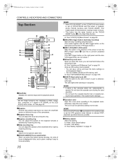
... this button during the eject operation. X See "LCD/VF[1/4] Menu Screen" on page 89. 8[REC] REC trigger button (start/stop recording) Start and stop recording using this button. (This works together with FOCUS ASSIST. When an SD memory card is pressed in the direction of field shallower, making ... playback operations become possible. MEMO Set the image format for the viewfinder to focus accurately. 18 MEMO • When FOCUS ASSIST on GY-HD250/GY-HD251. • You can adjust the position of the viewfinder left or right by loosening this button is pressed, ACCU FOCUS functions ...
... this button during the eject operation. X See "LCD/VF[1/4] Menu Screen" on page 89. 8[REC] REC trigger button (start/stop recording) Start and stop recording using this button. (This works together with FOCUS ASSIST. When an SD memory card is pressed in the direction of field shallower, making ... playback operations become possible. MEMO Set the image format for the viewfinder to focus accurately. 18 MEMO • When FOCUS ASSIST on GY-HD250/GY-HD251. • You can adjust the position of the viewfinder left or right by loosening this button is pressed, ACCU FOCUS functions ...
117 page operator's manual for the GY-HD250U
Page 23
... entered, the playback video will occur. h[STOP] Stop button Press to enter the stop or rewind mode initiates the fast forward mode. (Only for audio recording level. When this button in the stop mode. k[FF] Fast forward button Press this button to fast forward the tape. • Pressing this setting is...
... entered, the playback video will occur. h[STOP] Stop button Press to enter the stop or rewind mode initiates the fast forward mode. (Only for audio recording level. When this button in the stop mode. k[FF] Fast forward button Press this button to fast forward the tape. • Pressing this setting is...
117 page operator's manual for the GY-HD250U
Page 24
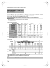
... terminal in DV format. (Select in the VIDEO FORMAT menu screen. q : Same format as the left. „ When recording camera images HD (HDV) DV HD Recording (Shooting) [REC] menu item Format HDV-HD60P 720/60p HDV-HD30P 720/30p HDV-HD50P 720/50p HDV-HD25P 720/25p ...1080I CAMERA] menu item Frame rate 60/30 ON 50/25 Rec on Tape q q q q q q q q q q Rec on the VIDEO FORMAT[2/2] menu screen) During recording and playback, image formats from external devices. N/A : Terminal is output. e_hd250.book Page 20 Tuesday, October 24, 2006 3:11 PM CONTROLS, INDICATORS AND CONNECTORS...
... terminal in DV format. (Select in the VIDEO FORMAT menu screen. q : Same format as the left. „ When recording camera images HD (HDV) DV HD Recording (Shooting) [REC] menu item Format HDV-HD60P 720/60p HDV-HD30P 720/30p HDV-HD50P 720/50p HDV-HD25P 720/25p ...1080I CAMERA] menu item Frame rate 60/30 ON 50/25 Rec on Tape q q q q q q q q q q Rec on the VIDEO FORMAT[2/2] menu screen) During recording and playback, image formats from external devices. N/A : Terminal is output. e_hd250.book Page 20 Tuesday, October 24, 2006 3:11 PM CONTROLS, INDICATORS AND CONNECTORS...
117 page operator's manual for the GY-HD250U
Page 25
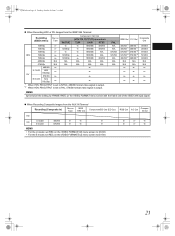
e_hd250.book Page 21 Tuesday, October 24, 2006 3:11 PM „ When Recording HDV or DV Images from the AUX IN Terminal Recording (Composite In) Rec on IEEE Tape 1394 Out Component/SDI Out (EE Out) HD U model 480/60i q q q SD E model 576/50i q q q MEMO • For the U ... the setting for FRAME RATE on the VIDEO FORMAT menu screen with the frame rate of the IEEE1394 input signal. „ When Recording Composite Images from the IEEE1394 Terminal HDV Recording (IEEE1394 In) 720/60p 720/30p 720/50p 720/25p 720/24p Rec on the VIDEO FORMAT[1/2] menu screen to PAL...
e_hd250.book Page 21 Tuesday, October 24, 2006 3:11 PM „ When Recording HDV or DV Images from the AUX IN Terminal Recording (Composite In) Rec on IEEE Tape 1394 Out Component/SDI Out (EE Out) HD U model 480/60i q q q SD E model 576/50i q q q MEMO • For the U ... the setting for FRAME RATE on the VIDEO FORMAT menu screen with the frame rate of the IEEE1394 input signal. „ When Recording Composite Images from the IEEE1394 Terminal HDV Recording (IEEE1394 In) 720/60p 720/30p 720/50p 720/25p 720/24p Rec on the VIDEO FORMAT[1/2] menu screen to PAL...
117 page operator's manual for the GY-HD250U
Page 28
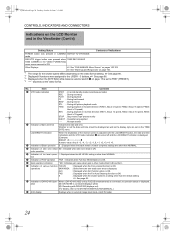
...8 Gain operation indication * dB : Indicates gain value when gain is ON. Item Contents 2 VTR mode indication STBY : In record standby mode (record-pause mode) REC : During recording PLAY : During playback FF : During fast forward REW : During rewind STL : During still picture playback mode FWD : During playback... *1 The range for the shutter speed differs depending on the video format setting. ation [: DR-HD100 is connected (displays white) [: Recording with the LCD BRIGHT button, the date and time indications and the VTR mode indication 2 are turned off and the LCD BRIGHT indicator ...
...8 Gain operation indication * dB : Indicates gain value when gain is ON. Item Contents 2 VTR mode indication STBY : In record standby mode (record-pause mode) REC : During recording PLAY : During playback FF : During fast forward REW : During rewind STL : During still picture playback mode FWD : During playback... *1 The range for the shutter speed differs depending on the video format setting. ation [: DR-HD100 is connected (displays white) [: Recording with the LCD BRIGHT button, the date and time indications and the VTR mode indication 2 are turned off and the LCD BRIGHT indicator ...

