

Instruction Manual
Page 1
... on the body. Before operating this information for purchasing this JVC product. For Customer Use : Enter below the Serial No. Retain this unit, please read the instructions carefully to ensure the best possible performance. DV CAMCORDER GY-DV550 INSTRUCTIONS INTRODUCTION CONTROLS, INDICATORS AND CONNECTORS BASIC SYSTEM CONNECTIONS AND ... (Super Scene Finder) FUNCTION USING EXTERNAL COMPONENTS SETUP MENU FEATURES OF THE CAMERA SECTION OTHERS * The illustration shows the GY-DV550 DV Camcorder with the optional lens viewfinder attached. Thank you for future reference. SC96999-002...
... on the body. Before operating this information for purchasing this JVC product. For Customer Use : Enter below the Serial No. Retain this unit, please read the instructions carefully to ensure the best possible performance. DV CAMCORDER GY-DV550 INSTRUCTIONS INTRODUCTION CONTROLS, INDICATORS AND CONNECTORS BASIC SYSTEM CONNECTIONS AND ... (Super Scene Finder) FUNCTION USING EXTERNAL COMPONENTS SETUP MENU FEATURES OF THE CAMERA SECTION OTHERS * The illustration shows the GY-DV550 DV Camcorder with the optional lens viewfinder attached. Thank you for future reference. SC96999-002...

Instruction Manual
Page 4
...remote control unit. The following phenomena may occur when tapes recorded on other units (including another GY-DV550) are for purchasing the DV Camcorder GY-DV550. Other use of magnesium die cast. ● DV high-quality digital format The 4:1:1, 8-bit, 25 Mbps component digital processing of the format ... unit. These instructions are recorded or played back on this camcorder. ● The transient section between scenes recorded on other units and those recorded on the rights of copyright holders. ● JVC cannot assume liabilities that may appear during playback due to the...
...remote control unit. The following phenomena may occur when tapes recorded on other units (including another GY-DV550) are for purchasing the DV Camcorder GY-DV550. Other use of magnesium die cast. ● DV high-quality digital format The 4:1:1, 8-bit, 25 Mbps component digital processing of the format ... unit. These instructions are recorded or played back on this camcorder. ● The transient section between scenes recorded on other units and those recorded on the rights of copyright holders. ● JVC cannot assume liabilities that may appear during playback due to the...

Instruction Manual
Page 6
... CALL RM OFF DC IN /BATT. OTHERS 14-1 Troubleshooting 96 • Alarm Indications 96 • Warnings in Viewfinder 98 • Troubles with DV Connector 70 11-2 Connecting a PC 71 12. Be sure to Select from the Camera Menu 77 12-4 VF Display Screen 78 12-5 OPERATION Screen... Setup Menu Contents 74 12-2 Camera Menu Screen Flow 76 12-3 How to remove the unit from the tripod. INTRODUCTION 1-1 Main Unit Configuration The GY-DV550 configuration is not inserted into the hole on a Computer Monitor 88 13-4 Gain (Sensitivity) Adjustment 89 • Gain Switching 89 • Gain Boost...
... CALL RM OFF DC IN /BATT. OTHERS 14-1 Troubleshooting 96 • Alarm Indications 96 • Warnings in Viewfinder 98 • Troubles with DV Connector 70 11-2 Connecting a PC 71 12. Be sure to Select from the Camera Menu 77 12-4 VF Display Screen 78 12-5 OPERATION Screen... Setup Menu Contents 74 12-2 Camera Menu Screen Flow 76 12-3 How to remove the unit from the tripod. INTRODUCTION 1-1 Main Unit Configuration The GY-DV550 configuration is not inserted into the hole on a Computer Monitor 88 13-4 Gain (Sensitivity) Adjustment 89 • Gain Switching 89 • Gain Boost...
Instruction Manual
Page 7
.... ● Cleaning the body: Wipe body with a dry, soft cloth. Otherwise the tape may be incorrect if the camera is played back, the GY-DV550 automatically enters the STOP mode. If this is not a malfunction. ● If a tape containing recorded PAL signals is used for a long period ●... the unit is not a camera malfunction. ● Noise may be damaged. ● The sensitivity level of the unit. When storing the GY-DV550 for transportation Do not drop or hit the unit against penetration of dust when using or placing the unit in places; • subject to ...
.... ● Cleaning the body: Wipe body with a dry, soft cloth. Otherwise the tape may be incorrect if the camera is played back, the GY-DV550 automatically enters the STOP mode. If this is not a malfunction. ● If a tape containing recorded PAL signals is used for a long period ●... the unit is not a camera malfunction. ● Noise may be damaged. ● The sensitivity level of the unit. When storing the GY-DV550 for transportation Do not drop or hit the unit against penetration of dust when using or placing the unit in places; • subject to ...

Instruction Manual
Page 8
...is used approximately 100 times. "HEAD CLOG" indicator 1-4 Precautions for a while. INTRODUCTION 1-3 Routine and Periodical Maintenance The GY-DV550 incorporates precision mechanical parts, which shows the accumulated drum running time. To prevent wear and deterioration, clean the mechanical parts ... interrupted. On the other than four times at your nearest JVC-authorized service agent. Head Cleaning ● To maintain beautiful pictures and sound, be conducted at your nearest JVC-authorized service agent. Running Time Drum ass'y (including heads...
...is used approximately 100 times. "HEAD CLOG" indicator 1-4 Precautions for a while. INTRODUCTION 1-3 Routine and Periodical Maintenance The GY-DV550 incorporates precision mechanical parts, which shows the accumulated drum running time. To prevent wear and deterioration, clean the mechanical parts ... interrupted. On the other than four times at your nearest JVC-authorized service agent. Head Cleaning ● To maintain beautiful pictures and sound, be conducted at your nearest JVC-authorized service agent. Running Time Drum ass'y (including heads...

Instruction Manual
Page 9
1-5 Videocassette to be Used ● Use JVC's videocassette tapes marked with a Switch switch on the back for this unit is placed in a very humid place. Another effect is a characteristic of the battery ... required recording SAVE in fine mesh patterns. This is the expansion of the unit does not increase. 9 Do not 1-6 Battery Pack to be Used The GY-DV550 can cause CCD sensor pixels to malfunction with the effect of a CCD it to a warm place, the moisture contained in the warm air may cause...
1-5 Videocassette to be Used ● Use JVC's videocassette tapes marked with a Switch switch on the back for this unit is placed in a very humid place. Another effect is a characteristic of the battery ... required recording SAVE in fine mesh patterns. This is the expansion of the unit does not increase. 9 Do not 1-6 Battery Pack to be Used The GY-DV550 can cause CCD sensor pixels to malfunction with the effect of a CCD it to a warm place, the moisture contained in the warm air may cause...

Instruction Manual
Page 12
... this dial. Pressing this dial once in the viewfinder. See "How to change the setting value of a warning or other abnormal condition occurring with the GY-DV550. This will be shot. COMPRESS : When an entire image is relatively light and the contrast is low, the gain of the full auto shooting functions...
... this dial. Pressing this dial once in the viewfinder. See "How to change the setting value of a warning or other abnormal condition occurring with the GY-DV550. This will be shot. COMPRESS : When an entire image is relatively light and the contrast is low, the gain of the full auto shooting functions...

Instruction Manual
Page 13
...to ON while a videocassette is shot, the auto knee function may change the brightness of the entire image along with the motion of the GY-DV550 with the OPERATION MENU (see page 79). This function is not available. When a recordable videocassette is available. CAUTION: If a fast moving...illumination on page 68. $ [OPERATE] switch Turn the power ON and OFF with this button while recording or in sunlight is loaded, the GY-DV550 status differs depending on page 90. 9 [GAIN] switch Electronically boosts the light sensitivity when there is in PROCESS MENU screen. See "S.S.F. (Super...
...to ON while a videocassette is shot, the auto knee function may change the brightness of the entire image along with the motion of the GY-DV550 with the OPERATION MENU (see page 79). This function is not available. When a recordable videocassette is available. CAUTION: If a fast moving...illumination on page 68. $ [OPERATE] switch Turn the power ON and OFF with this button while recording or in sunlight is loaded, the GY-DV550 status differs depending on page 90. 9 [GAIN] switch Electronically boosts the light sensitivity when there is in PROCESS MENU screen. See "S.S.F. (Super...

Instruction Manual
Page 15
...recalls the previous display contents. • In setup menu mode, this button to select the digit to the VTR/RM multi-pin connector of the DV connector 1 on page 69. REC : Preset mode. Set to this unit or an external VCR connected to be set. Set to this compartment.... to record camera images or composite video from the GENLOCK/AUX IN connector are also outputted to install a new lithium battery. The set . The GY-DV550 delivered without the battery installed. mode, time code generator will be started and stopped by 1. • In setup menu mode, this button is ...
...recalls the previous display contents. • In setup menu mode, this button to select the digit to the VTR/RM multi-pin connector of the DV connector 1 on page 69. REC : Preset mode. Set to this unit or an external VCR connected to be set. Set to this compartment.... to record camera images or composite video from the GENLOCK/AUX IN connector are also outputted to install a new lithium battery. The set . The GY-DV550 delivered without the battery installed. mode, time code generator will be started and stopped by 1. • In setup menu mode, this button is ...

Instruction Manual
Page 16
... playback and in the record mode or EE mode. OFF : The display is not illuminated. (Keep this switch at OFF during battery operation of the GY-DV550 or when it is required to reduce the power consumption for presetting the time code. (When the Menu item No. 516 DISPLAY SELECT is set...
... playback and in the record mode or EE mode. OFF : The display is not illuminated. (Keep this switch at OFF during battery operation of the GY-DV550 or when it is required to reduce the power consumption for presetting the time code. (When the Menu item No. 516 DISPLAY SELECT is set...

Instruction Manual
Page 17
...). • This section shows an error code when an abnormal condition occurs with the 4 COUNTER switch. • Displays the VCR setup menu data when the GY-DV550 is slave-locked (synchronized) with the LTC time code signal input at the TC IN connector. See "Displaying Time Code" on page 8. [Li] Lithium indicator...
...). • This section shows an error code when an abnormal condition occurs with the 4 COUNTER switch. • Displays the VCR setup menu data when the GY-DV550 is slave-locked (synchronized) with the LTC time code signal input at the TC IN connector. See "Displaying Time Code" on page 8. [Li] Lithium indicator...

Instruction Manual
Page 18
..., INDICATORS AND CONNECTORS 2-3 Left Side Section PUSH q w e VTR/RM DV CAMCORDER GY-DV550 PROMPTER OUTPUT Y/C OUT MONITOR OUT LINE OUT CH-1 CH-2 TC IN TC...signal. For the slave lock of the Camera Setup screen. The following video signals are inputted when the GY-DV550's camera image is not output. 7 [VIDEO OUT] Video output connector (BNC) Connector for composite video...microphone holder KA-A50 (optional). Which video signals to RM, this unit. For details, please consult your JVC dealer. Note: If you make an error in time code generator can be slave-locked with setting the ...
..., INDICATORS AND CONNECTORS 2-3 Left Side Section PUSH q w e VTR/RM DV CAMCORDER GY-DV550 PROMPTER OUTPUT Y/C OUT MONITOR OUT LINE OUT CH-1 CH-2 TC IN TC...signal. For the slave lock of the Camera Setup screen. The following video signals are inputted when the GY-DV550's camera image is not output. 7 [VIDEO OUT] Video output connector (BNC) Connector for composite video...microphone holder KA-A50 (optional). Which video signals to RM, this unit. For details, please consult your JVC dealer. Note: If you make an error in time code generator can be slave-locked with setting the ...

Instruction Manual
Page 21
... connector 8. 21 Set MODE switch 6 according to connect an external VCR or camera control unit. 2. CONTROLS, INDICATORS AND CONNECTORS 2-5 Adapter Section (continued) PUSH 7 8 9 VTR/RM DV CAMCORDER GY-DV550 PROMPTER OUTPUT Y/C OUT MONITOR OUT LINE OUT CH-1 CH-2 TC IN TC OUT REMOTE GENLOCK/AUX IN VIDEO OUT AUDIO IN FRONT LENS 8 [VTR/RM...
... connector 8. 21 Set MODE switch 6 according to connect an external VCR or camera control unit. 2. CONTROLS, INDICATORS AND CONNECTORS 2-5 Adapter Section (continued) PUSH 7 8 9 VTR/RM DV CAMCORDER GY-DV550 PROMPTER OUTPUT Y/C OUT MONITOR OUT LINE OUT CH-1 CH-2 TC IN TC OUT REMOTE GENLOCK/AUX IN VIDEO OUT AUDIO IN FRONT LENS 8 [VTR/RM...
Instruction Manual
Page 22
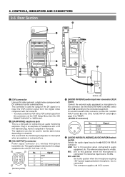
...the microphone is a mini-jack for connecting an audio monitoring earphone. CONTROLS, INDICATORS AND CONNECTORS 2-6 Rear Section !0 PUSH o VTR/RM DV CAMCORD GY-DV550 q w e DV LINE EARPHONE DC OUTPUT MIC +48V ON LINE MIC +48V ON FRONT AUDIO IN REAR INTERCOM DC INPUT t y r ui PROMPTER ...OUTPUT Y/C OUT MONITOR OUT LINE OUT CH-1 CH-2 !1 TC IN TC OUT REMOT BREAKER 1 [DV] connector Using a DV cable (optional), a digital video component with DV connector can also be connected here. This connector is -60 dBs. Signal 1 GND 2 HOT 3 COLD 5 [AUDIO ...
...the microphone is a mini-jack for connecting an audio monitoring earphone. CONTROLS, INDICATORS AND CONNECTORS 2-6 Rear Section !0 PUSH o VTR/RM DV CAMCORD GY-DV550 q w e DV LINE EARPHONE DC OUTPUT MIC +48V ON LINE MIC +48V ON FRONT AUDIO IN REAR INTERCOM DC INPUT t y r ui PROMPTER ...OUTPUT Y/C OUT MONITOR OUT LINE OUT CH-1 CH-2 !1 TC IN TC OUT REMOT BREAKER 1 [DV] connector Using a DV cable (optional), a digital video component with DV connector can also be connected here. This connector is -60 dBs. Signal 1 GND 2 HOT 3 COLD 5 [AUDIO ...

Instruction Manual
Page 25
.... To activate the auto iris feature, set the Iris Mode switch 7 to A. 4 [VTR] Trigger button To start/stop shooting. 5 [RET] return video button • When GY-DV550 is in the record-pause or stop mode, press this button to check the immediately preceding image recorded. • When the camera control unit is...
.... To activate the auto iris feature, set the Iris Mode switch 7 to A. 4 [VTR] Trigger button To start/stop shooting. 5 [RET] return video button • When GY-DV550 is in the record-pause or stop mode, press this button to check the immediately preceding image recorded. • When the camera control unit is...

Instruction Manual
Page 27
...BATT] battery lamp This lights red when the battery voltage becomes too low for use in the VCR. Blinks green : • While the GY-DV550 switches from record-pause to show one of status screen 0 and 1 and camera setting related display will not be displayed every time the ... During recording. The external VCR status is displayed when VTR SELECT switch is playing back a tape.) Status screens (screens for use in the GY-DV550. The following circumstances. In addition, AUX will appear on the viewfinder screen. (However, this information is not displayed while the VCR section is...
...BATT] battery lamp This lights red when the battery voltage becomes too low for use in the VCR. Blinks green : • While the GY-DV550 switches from record-pause to show one of status screen 0 and 1 and camera setting related display will not be displayed every time the ... During recording. The external VCR status is displayed when VTR SELECT switch is playing back a tape.) Status screens (screens for use in the GY-DV550. The following circumstances. In addition, AUX will appear on the viewfinder screen. (However, this information is not displayed while the VCR section is...

Instruction Manual
Page 32
... page explaining the respective connection methods. Please use the Focus Manual Unit (FMM-8, CHF-3, CFC-12-990) manufactured by Fujinon. 32 POWER GY-DV550 STANDARD PACKAGE TRIPOD BASE VIDEO LIGHT (ANTON BAUER. 3. BASIC SYSTEM CONNECTIONS AND ADJUSTMENTS 3-1 Basic System For information on connection with S14X7.3B12...CAMERA REMOTE CONTROL UNIT RM-P200 RM-P300 BATTERY NP-1B TYPE BATTERY NP-1B TYPE BATTERY CHARGER 1.5" VIEW FINDER VF-P115B VF-P116 DV CAMCORDER BATTERY HOLDER BH-P27 BATTERY NB-G1 NB-G1 (4PACK) BATTERY CHARGER (AC POWER ADAPTER) AA-G11 ZOOM LENS S14 x 7.3B12(...
... page explaining the respective connection methods. Please use the Focus Manual Unit (FMM-8, CHF-3, CFC-12-990) manufactured by Fujinon. 32 POWER GY-DV550 STANDARD PACKAGE TRIPOD BASE VIDEO LIGHT (ANTON BAUER. 3. BASIC SYSTEM CONNECTIONS AND ADJUSTMENTS 3-1 Basic System For information on connection with S14X7.3B12...CAMERA REMOTE CONTROL UNIT RM-P200 RM-P300 BATTERY NP-1B TYPE BATTERY NP-1B TYPE BATTERY CHARGER 1.5" VIEW FINDER VF-P115B VF-P116 DV CAMCORDER BATTERY HOLDER BH-P27 BATTERY NB-G1 NB-G1 (4PACK) BATTERY CHARGER (AC POWER ADAPTER) AA-G11 ZOOM LENS S14 x 7.3B12(...

Instruction Manual
Page 35
... it . 5. 3. Safety lever 4. POWER 3-7 Attaching the 4-inch Viewfinder (Optional) VF-P400 Lock lever mount screw stopper pin mount screw KA-A40 PUSH handle VTR/RM DV CAMCORDER GY-DV550 PROMPTER OUTPUT Y/C OUT MONITOR OUT LINE OUT CH-1 CH-2 TC IN TC OUT REMOTE GENLOCK/AUX IN VIDEO OUT AUDIO IN FRONT LENS Use the...
... it . 5. 3. Safety lever 4. POWER 3-7 Attaching the 4-inch Viewfinder (Optional) VF-P400 Lock lever mount screw stopper pin mount screw KA-A40 PUSH handle VTR/RM DV CAMCORDER GY-DV550 PROMPTER OUTPUT Y/C OUT MONITOR OUT LINE OUT CH-1 CH-2 TC IN TC OUT REMOTE GENLOCK/AUX IN VIDEO OUT AUDIO IN FRONT LENS Use the...

Instruction Manual
Page 36
... lithium battery cover to Install the Lithium Battery Lithium battery cover LITHIUM BATT. BASIC SYSTEM CONNECTIONS AND ADJUSTMENTS 3-8 Inserting and Replacing Backup Lithium Batteries The GY-DV550 uses a lithium battery for a lengthy period of the arrow as illustrated and remove the cover. 2. How to its upward. Push the lithium battery cover in...
... lithium battery cover to Install the Lithium Battery Lithium battery cover LITHIUM BATT. BASIC SYSTEM CONNECTIONS AND ADJUSTMENTS 3-8 Inserting and Replacing Backup Lithium Batteries The GY-DV550 uses a lithium battery for a lengthy period of the arrow as illustrated and remove the cover. 2. How to its upward. Push the lithium battery cover in...

Instruction Manual
Page 37
... AC power adapter (max. Note: Do not remove or connect the DC cable while recording is not equipped with a ferrite core, please contact your JVC dealer. 1. FILTER 1 3200k 2 5600k+1/8ND 3 5600k+1/64ND SHUTTER STATUS MENU ALARM MONITOR AUTO IRIS FULL AUTO BLACK BACK L NORMAL SPOT L STRETCH...disconnected while operating with large fluctuations in the illustration. 2. Remove the battery pack when the GY-DV550 is interrupted and the power starts to OFF. 4. AA-P250 AC power adapter DC cable DV LINE EARPHONE DC OUTPUT MIC +48V ON LINE MIC +48V ON FRONT AUDIO IN REAR ...
... AC power adapter (max. Note: Do not remove or connect the DC cable while recording is not equipped with a ferrite core, please contact your JVC dealer. 1. FILTER 1 3200k 2 5600k+1/8ND 3 5600k+1/64ND SHUTTER STATUS MENU ALARM MONITOR AUTO IRIS FULL AUTO BLACK BACK L NORMAL SPOT L STRETCH...disconnected while operating with large fluctuations in the illustration. 2. Remove the battery pack when the GY-DV550 is interrupted and the power starts to OFF. 4. AA-P250 AC power adapter DC cable DV LINE EARPHONE DC OUTPUT MIC +48V ON LINE MIC +48V ON FRONT AUDIO IN REAR ...


