
Instructions
Page 1
and Serial No. which are located either on the rear, bottom or side of RX-EXA10, SP-EXA10 and XV-EXA10 INSTRUCTIONS For Customer Use: Enter below the Model No. Serial No. English COMPACT COMPONENT SYSTEM EX-A10 Consists of the cabinet. LVT1403-002B [J, C, UJ] Model No. Retain this information for future reference.
and Serial No. which are located either on the rear, bottom or side of RX-EXA10, SP-EXA10 and XV-EXA10 INSTRUCTIONS For Customer Use: Enter below the Model No. Serial No. English COMPACT COMPONENT SYSTEM EX-A10 Consists of the cabinet. LVT1403-002B [J, C, UJ] Model No. Retain this information for future reference.
Instructions
Page 2
The exclamation point within the product's enclosure that may cause harmful interference to which can radiate radio frequency energy and, if not installed and used in accordance with the instructions, may be determined by turning the equipment off and on a circuit different from that to radio communications. Increase the separation between the equipment and receiver. Connect the equipment into an outlet on , the user is encouraged to try to correct the interference by one or more of the following measures: Reorient or relocate the receiving antenna. Consult the dealer or an ...
The exclamation point within the product's enclosure that may cause harmful interference to which can radiate radio frequency energy and, if not installed and used in accordance with the instructions, may be determined by turning the equipment off and on a circuit different from that to radio communications. Increase the separation between the equipment and receiver. Connect the equipment into an outlet on , the user is encouraged to try to correct the interference by one or more of the following measures: Reorient or relocate the receiving antenna. Consult the dealer or an ...
Instructions
Page 6
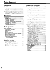
...TV using the remote control......... 6 Preparation Connections 7 Standard setup 7 Connecting the antennas 7 Connecting the speakers 9 Connecting the receiver and the DVD player ... 10 Connecting other equipment 11 Connecting a TV 12 Connecting the power cords 13 Basic operations Basic operations 14 Turning on/off the ...post exchanges 18 Selecting a radio station 18 Tuning in to a preset radio station 19 Playing back DVDs/CDs Basic operations of the DVD player 20 Playing back a DVD/CD 20 Changing the display in the display window ......23 Selecting a chapter/track using the number ...
...TV using the remote control......... 6 Preparation Connections 7 Standard setup 7 Connecting the antennas 7 Connecting the speakers 9 Connecting the receiver and the DVD player ... 10 Connecting other equipment 11 Connecting a TV 12 Connecting the power cords 13 Basic operations Basic operations 14 Turning on/off the ...post exchanges 18 Selecting a radio station 18 Tuning in to a preset radio station 19 Playing back DVDs/CDs Basic operations of the DVD player 20 Playing back a DVD/CD 20 Changing the display in the display window ......23 Selecting a chapter/track using the number ...
Instructions
Page 7
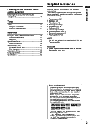
... items supplied. How to read this manual. • The following marks refer to the usable discs for the explained function. • "DVD VR" means a DVD recorded in DVD Video Recording (DVD VR) format. • "VCD" stands for "Video Compact Disc". • "SVCD" stands for "Super Video Compact Disc". •... on the remote control. CAUTION • Do not fold the optical digital cord as those on handling 46 About DVDs/CDs 47 Playable DVD/CD types 47 Disc structure 49 Troubleshooting 50 Language codes 51 Specifications 52 Introduction Supplied accessories Check to be sure you...
... items supplied. How to read this manual. • The following marks refer to the usable discs for the explained function. • "DVD VR" means a DVD recorded in DVD Video Recording (DVD VR) format. • "VCD" stands for "Video Compact Disc". • "SVCD" stands for "Super Video Compact Disc". •... on the remote control. CAUTION • Do not fold the optical digital cord as those on handling 46 About DVDs/CDs 47 Playable DVD/CD types 47 Disc structure 49 Troubleshooting 50 Language codes 51 Specifications 52 Introduction Supplied accessories Check to be sure you...
Instructions
Page 8
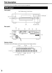
Part description The numbers refer to the pages in which the parts are explained. DVD player Front panel See "Display window" shown below. 5 13, 14 14 23-26, 28 Rear panel 10 13 45 10 20 20, 28 20, 24 10 47 12 12 12 Display window The receiver and the DVD player use the same design for their display windows. 21, 22 34, 35 13 21, 22 21, 27 28 30 30 31 31 21, 22, 29 21, 22, 29 3
Part description The numbers refer to the pages in which the parts are explained. DVD player Front panel See "Display window" shown below. 5 13, 14 14 23-26, 28 Rear panel 10 13 45 10 20 20, 28 20, 24 10 47 12 12 12 Display window The receiver and the DVD player use the same design for their display windows. 21, 22 34, 35 13 21, 22 21, 27 28 30 30 31 31 21, 22, 29 21, 22, 29 3
Instructions
Page 9
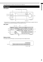
When the headphones are explained. Receiver Front panel See "Display window" shown below. 5 18 13, 14 14, 18 16 * 17 18, 20, 41 * This terminal is for their display windows. 15, 18 18 43 42 4 Introduction The numbers refer to the pages in which the parts are connected, the speakers do not produce any sound. Rear panel 12 10 10 9, 11 10 7 11 12 8 13 Display window The receiver and the DVD player use the same design for connecting a pair of headphones equipped with a stereo plug (not supplied).
When the headphones are explained. Receiver Front panel See "Display window" shown below. 5 18 13, 14 14, 18 16 * 17 18, 20, 41 * This terminal is for their display windows. 15, 18 18 43 42 4 Introduction The numbers refer to the pages in which the parts are connected, the speakers do not produce any sound. Rear panel 12 10 10 9, 11 10 7 11 12 8 13 Display window The receiver and the DVD player use the same design for connecting a pair of headphones equipped with a stereo plug (not supplied).
Instructions
Page 10
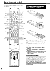
... 15, 29, 44 11 16 16 11, 17 If the effective distance between the remote control and remote control sensor on the receiver or the DVD player decreases, replace the batteries. CAUTION • Do not use a used for a long time. Otherwise it at the same time. • Take out the batteries... not be used battery and a new battery together. • Do not use different types of batteries at the front panel of the receiver or the DVD player.
... 15, 29, 44 11 16 16 11, 17 If the effective distance between the remote control and remote control sensor on the receiver or the DVD player decreases, replace the batteries. CAUTION • Do not use a used for a long time. Otherwise it at the same time. • Take out the batteries... not be used battery and a new battery together. • Do not use different types of batteries at the front panel of the receiver or the DVD player.
Instructions
Page 11
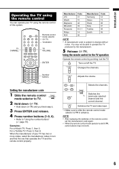
... work. 6 Using the remote control for the TV operation Operate the remote control by the manufacturer. 5 Release F TV. For a Toshiba TV: Press 0, then 8. Manufacturer Code JVC 01 Hitachi 10 Magnavox 02 Mitsubishi 03 Panasonic 04, 11 Philips 14 RCA 05 Manufacturer Samsung Sanyo Sharp Sony Toshiba Zenith Code 12 13 06...
... work. 6 Using the remote control for the TV operation Operate the remote control by the manufacturer. 5 Release F TV. For a Toshiba TV: Press 0, then 8. Manufacturer Code JVC 01 Hitachi 10 Magnavox 02 Mitsubishi 03 Panasonic 04, 11 Philips 14 RCA 05 Manufacturer Samsung Sanyo Sharp Sony Toshiba Zenith Code 12 13 06...
Instructions
Page 12
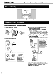
... to "Listening to radio broadcasts" (A page 18)). 7 Receiver (rear panel) White Black 3 Turn the AM loop antenna to find the best position for radio reception. DVD player Speaker Receiver Speaker Connecting the antennas Connecting the AM loop antenna (supplied) 1 Set up the AM loop antenna. 2 Connect the antenna cord. Connections Standard...
... to "Listening to radio broadcasts" (A page 18)). 7 Receiver (rear panel) White Black 3 Turn the AM loop antenna to find the best position for radio reception. DVD player Speaker Receiver Speaker Connecting the antennas Connecting the AM loop antenna (supplied) 1 Set up the AM loop antenna. 2 Connect the antenna cord. Connections Standard...
Instructions
Page 13
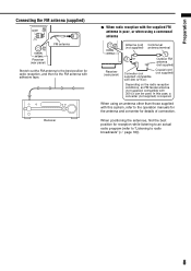
When positioning the antennas, find the best position for details of connection. Preparation Connecting the FM antenna (supplied) FM antenna Receiver (rear panel) Stretch out the FM antenna to radio broadcasts" (A page 18)). 8 Receiver 7 When radio reception with the supplied FM antenna is poor, or when using an antenna other than those supplied with this case, a converter (not supplied) is required. In this system, refer to the operation manuals for the antenna and converter for reception while listening to an actual radio program (refer to "Listening to the best position for ...
When positioning the antennas, find the best position for details of connection. Preparation Connecting the FM antenna (supplied) FM antenna Receiver (rear panel) Stretch out the FM antenna to radio broadcasts" (A page 18)). 8 Receiver 7 When radio reception with the supplied FM antenna is poor, or when using an antenna other than those supplied with this case, a converter (not supplied) is required. In this system, refer to the operation manuals for the antenna and converter for reception while listening to an actual radio program (refer to "Listening to the best position for ...
Instructions
Page 14
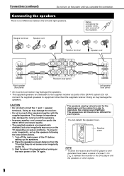
...Connecting the speakers There is no difference between the receiver or the DVD player and the speakers or other objects. 9 Turn off the insulation. Before connecting the speaker cords, twist and pull off the main power of the EX-A10 system. Doing so may damage the receiver and the speakers. &#...not cause color irregularity on the power until you complete the connection. Speaker cover NOTE • To allow the receiver and the DVD player to the supplied receiver as parts of the TV before turning on some conditions. The appearance will therefore be different for about...
...Connecting the speakers There is no difference between the receiver or the DVD player and the speakers or other objects. 9 Turn off the insulation. Before connecting the speaker cords, twist and pull off the main power of the EX-A10 system. Doing so may damage the receiver and the speakers. &#...not cause color irregularity on the power until you complete the connection. Speaker cover NOTE • To allow the receiver and the DVD player to the supplied receiver as parts of the TV before turning on some conditions. The appearance will therefore be different for about...
Instructions
Page 15
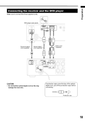
Protection cap 10 If protection caps cover the tips of the optical digital cord, pull off the protection caps before connecting. DVD player (rear panel) Synchronization cord (supplied) Optical digital cord (supplied) Audio cord (supplied) CAUTION • Do not fold the optical digital cord as this may damage the inner wire. Preparation Connecting the receiver and the DVD player Make sure to connect the three supplied cords.
Protection cap 10 If protection caps cover the tips of the optical digital cord, pull off the protection caps before connecting. DVD player (rear panel) Synchronization cord (supplied) Optical digital cord (supplied) Audio cord (supplied) CAUTION • Do not fold the optical digital cord as this may damage the inner wire. Preparation Connecting the receiver and the DVD player Make sure to connect the three supplied cords.
Instructions
Page 16
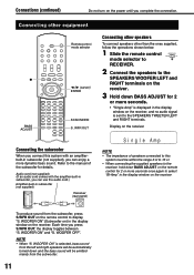
WOOFER OFF". Each time you can enjoy a more seconds. • "Single Amp" is displayed in the display window on the receiver. 3 Hold down BASS ADJUST for 2 or more seconds once again to select "Bi-Amp" in subwoofer (not supplied) Receiver (rear panel) NOTE • The impedance of the subwoofer for details. WOOFER ON" (Subwoofer on) in the display window on the power until you can use the audio cord.) Amplifier-built-in the display window on the remote control to the receiver, hold down and the bass sound will be emitted mainly from the subwoofer. 11 WOOFER ON" ...
WOOFER OFF". Each time you can enjoy a more seconds. • "Single Amp" is displayed in the display window on the receiver. 3 Hold down BASS ADJUST for 2 or more seconds once again to select "Bi-Amp" in subwoofer (not supplied) Receiver (rear panel) NOTE • The impedance of the subwoofer for details. WOOFER ON" (Subwoofer on) in the display window on the power until you can use the audio cord.) Amplifier-built-in the display window on the remote control to the receiver, hold down and the bass sound will be emitted mainly from the subwoofer. 11 WOOFER ON" ...
Instructions
Page 17
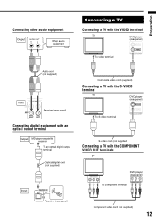
Preparation Connecting other audio equipment Output Other audio equipment Connecting a TV Connecting a TV with the VIDEO terminal TV DVD player (rear panel) To video terminal Audio cord (not supplied) Input Receiver (rear panel) Connecting digital equipment with an optical output terminal ... output terminal Optical digital cord (not supplied) Input Receiver (rear panel) Composite video cord (supplied) Connecting a TV with the S-VIDEO terminal TV DVD player (rear panel) To S-video terminal S-video cord (not supplied) Connecting a TV with the COMPONENT VIDEO OUT terminals TV...
Preparation Connecting other audio equipment Output Other audio equipment Connecting a TV Connecting a TV with the VIDEO terminal TV DVD player (rear panel) To video terminal Audio cord (not supplied) Input Receiver (rear panel) Connecting digital equipment with an optical output terminal ... output terminal Optical digital cord (not supplied) Input Receiver (rear panel) Composite video cord (supplied) Connecting a TV with the S-VIDEO terminal TV DVD player (rear panel) To S-video terminal S-video cord (not supplied) Connecting a TV with the COMPONENT VIDEO OUT terminals TV...
Instructions
Page 18
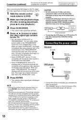
... is a conventional video signal type. • Select "INTERLACE" when a TV only compatible with interlaced video signals is connected to the DVD player. • Select "PROGRESSIVE" when a TV equipped with a component terminal and compatible with progressive video signals is connected to "INTERLACE... To check the compatibility of your TV, contact your local JVC customer service center. • All JVC-manufactured progressive TVs and highdefinition TVs are fully compatible with this case, change the scan mode to the DVD player. You can select "INTERLACE" or "PROGRESSIVE". The ...
... is a conventional video signal type. • Select "INTERLACE" when a TV only compatible with interlaced video signals is connected to the DVD player. • Select "PROGRESSIVE" when a TV equipped with a component terminal and compatible with progressive video signals is connected to "INTERLACE... To check the compatibility of your TV, contact your local JVC customer service center. • All JVC-manufactured progressive TVs and highdefinition TVs are fully compatible with this case, change the scan mode to the DVD player. You can select "INTERLACE" or "PROGRESSIVE". The ...

Instructions
Page 19
... • With the power off , pressing any of the receiver will turn off. • Press F DVD again to the button starts working at the same time. (When you press DVD on the remote control or 3/8 on the receiver. - Basic operations Turning on/off the system Receiver 1 Slide... F AUDIO again to the button starts working at the same time. DVD player 1 Slide the remote control mode selector to DVD. 2 Press F DVD (or F on the DVD player). • The power of the following buttons also turns on the DVD player, if a disc has been loaded, playback starts automatically.) 14 Number...
... • With the power off , pressing any of the receiver will turn off. • Press F DVD again to the button starts working at the same time. (When you press DVD on the remote control or 3/8 on the receiver. - Basic operations Turning on/off the system Receiver 1 Slide... F AUDIO again to the button starts working at the same time. DVD player 1 Slide the remote control mode selector to DVD. 2 Press F DVD (or F on the DVD player). • The power of the following buttons also turns on the DVD player, if a disc has been loaded, playback starts automatically.) 14 Number...
Instructions
Page 20
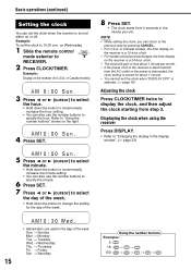
Example: Display on or off. or Canada models, the time display on the receiver is a 12-hour clock. • For models sold at post exchanges, the time display on the receiver is a 24-hour clock. • The clock will gain or lose about 1 minute per month. • If the power cord of the receiver is disconnected from the AC outlet or the power is interrupted, the clock setting is stored for about 1 minute. • You cannot set the clock when "DISPLAY OFF" is turned either on the receiver (for U.S.A. Displaying the clock when using the receiver Press DISPLAY. • Refer to "...
Example: Display on or off. or Canada models, the time display on the receiver is a 12-hour clock. • For models sold at post exchanges, the time display on the receiver is a 24-hour clock. • The clock will gain or lose about 1 minute per month. • If the power cord of the receiver is disconnected from the AC outlet or the power is interrupted, the clock setting is stored for about 1 minute. • You cannot set the clock when "DISPLAY OFF" is turned either on the receiver (for U.S.A. Displaying the clock when using the receiver Press DISPLAY. • Refer to "...
Instructions
Page 21
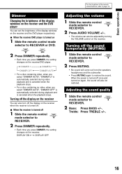
... windows on the receiver and the DVD player respectively. 7 When the receiver/DVD player is turned on 1 Slide the remote control mode selector to RECEIVER or DVD. 2 Press DIMMER repeatedly. • Each time you press DIMMER, the setting changes on the receiver/DVD player. DISPLAY ON DISPLAY OFF Adjusting...refer to RECEIVER. 2 Press MUTING. • No sound will also be adjusted by turning the VOLUME control on the receiver and the DVD player You can also turn off the display on the receiver. Dimmer Changing the brightness of the display windows on the receiver. Turning off ...
... windows on the receiver and the DVD player respectively. 7 When the receiver/DVD player is turned on 1 Slide the remote control mode selector to RECEIVER or DVD. 2 Press DIMMER repeatedly. • Each time you press DIMMER, the setting changes on the receiver/DVD player. DISPLAY ON DISPLAY OFF Adjusting...refer to RECEIVER. 2 Press MUTING. • No sound will also be adjusted by turning the VOLUME control on the receiver and the DVD player You can also turn off the display on the receiver. Dimmer Changing the brightness of the display windows on the receiver. Turning off ...
Instructions
Page 22
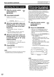
Display on the front panel of "Q" in the display window. • You can select "100 Hz", "120 Hz" or "140 Hz". • The initial setting is "100 Hz". Select the value for your desired bass sound. 5 Press ENTER. • The selected values are flashing, press 5 or / (cursor) to select the value of the receiver lights up. • Each time you press CC CONVERTER, the display changes as the sound source or when 3D PHONIC is activated (A page 35). Enhancing the playback sound (CC CONVERTER) The CC CONVERTER function is designed to approximate the original analog sound. The function ...
Display on the front panel of "Q" in the display window. • You can select "100 Hz", "120 Hz" or "140 Hz". • The initial setting is "100 Hz". Select the value for your desired bass sound. 5 Press ENTER. • The selected values are flashing, press 5 or / (cursor) to select the value of the receiver lights up. • Each time you press CC CONVERTER, the display changes as the sound source or when 3D PHONIC is activated (A page 35). Enhancing the playback sound (CC CONVERTER) The CC CONVERTER function is designed to approximate the original analog sound. The function ...
Instructions
Page 23
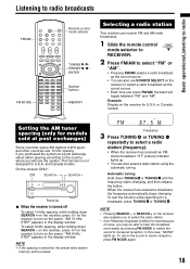
Example: Display on the receiver also enables you to select the radio station. • If an FM stereo broadcast is not designed for U.S.A. If you purchased the system at post exchanges) Some countries space AM stations 9 kHz apart, and other countries use 10 kHz spacing. and Canada models. "AM 9 kHz STEP" appears in the display window. or SEARCH + on the receiver for U.S.A. This function is difficult to hear because of noise, you may be erased. Automatic tuning: Hold down SEARCH - NOTE • Pressing SEARCH - In this case, "MONO" lights up . • You can ...
Example: Display on the receiver also enables you to select the radio station. • If an FM stereo broadcast is not designed for U.S.A. If you purchased the system at post exchanges) Some countries space AM stations 9 kHz apart, and other countries use 10 kHz spacing. and Canada models. "AM 9 kHz STEP" appears in the display window. or SEARCH + on the receiver for U.S.A. This function is difficult to hear because of noise, you may be erased. Automatic tuning: Hold down SEARCH - NOTE • Pressing SEARCH - In this case, "MONO" lights up . • You can ...
