Instruction Manual
Page 1
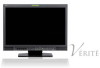
... of electric shock. Refer servicing to the presence of uninsulated "dangerous voltage" within an equilateral triangle is of DT-V24L3D. No user serviceable parts inside. DT-V24L3D DT-V20L3D MULTI FORMAT LCD MONITOR The illustration of the monitor is intended to alert the user to the presence of important operating and maintenance (servicing) instructions in the...
... of electric shock. Refer servicing to the presence of uninsulated "dangerous voltage" within an equilateral triangle is of DT-V24L3D. No user serviceable parts inside. DT-V24L3D DT-V20L3D MULTI FORMAT LCD MONITOR The illustration of the monitor is intended to alert the user to the presence of important operating and maintenance (servicing) instructions in the...
Instruction Manual
Page 4
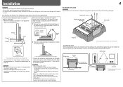
... holes for stand attachment Stand body Monitor The illustration of the monitor is attached to prevent the LCD panel from being damaged. - Monitor The illustration of the monitor is of DT-V24L3D. • You can tilt the monitor from about 6° downward. • When the monitor is attached to pinch your fingers in...correct position. The illustrations of the monitor are of DT-V24L3D. • To place the monitor as illustrated on the left again, remove the screws on the left and right sides of DT-V24L3D. lay the monitor on a cloth with the LCD panel facing down to the lower ...
... holes for stand attachment Stand body Monitor The illustration of the monitor is attached to prevent the LCD panel from being damaged. - Monitor The illustration of the monitor is of DT-V24L3D. • You can tilt the monitor from about 6° downward. • When the monitor is attached to pinch your fingers in...correct position. The illustrations of the monitor are of DT-V24L3D. • To place the monitor as illustrated on the left again, remove the screws on the left and right sides of DT-V24L3D. lay the monitor on a cloth with the LCD panel facing down to the lower ...
Instruction Manual
Page 5
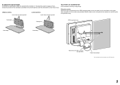
... for higher position Screw holes for lower position To prevent an accidental fall Fix the monitor to a wall by choosing the screw holes to use the two holes on the rear panel of DT-V24L3D. 5 Fixing the monitor Attach the hook (not provided) to the VESA mounting holes on page 4). Then, ...change the stand height, detach the stand from the monitor (☞ "To detach the stand" on the rear panel (use . ...
... for higher position Screw holes for lower position To prevent an accidental fall Fix the monitor to a wall by choosing the screw holes to use the two holes on the rear panel of DT-V24L3D. 5 Fixing the monitor Attach the hook (not provided) to the VESA mounting holes on page 4). Then, ...change the stand height, detach the stand from the monitor (☞ "To detach the stand" on the rear panel (use . ...
Instruction Manual
Page 6
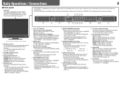
...; Adjust the settings of the wave form monitor in "SYNC FUNCTION" on page 7) t INPUT SELECT buttons/lamps Selects an input. SAVE (power save) mode (☞ "NO SYNC ACTION" in "WAVE FORM SETTING" of DT-V24L3D. 1 Speakers (stereo) The speakers emit the same audio signal emitted from 4:3... to 16:9 when the picture of the monitor is off (on page 8) 2 VOLUME adjustment knob Adjusts the volume. 3 Picture adjustment knob...
...; Adjust the settings of the wave form monitor in "SYNC FUNCTION" on page 7) t INPUT SELECT buttons/lamps Selects an input. SAVE (power save) mode (☞ "NO SYNC ACTION" in "WAVE FORM SETTING" of DT-V24L3D. 1 Speakers (stereo) The speakers emit the same audio signal emitted from 4:3... to 16:9 when the picture of the monitor is off (on page 8) 2 VOLUME adjustment knob Adjusts the volume. 3 Picture adjustment knob...
Instruction Manual
Page 7
..."STATUS DISPLAY" is set to select an audio channel. • Each time you change the input - On the Status Display If you turn on the monitor • When "STATUS DISPLAY" is activated. ☞ " 4 MUTING button" on page 6 On the signal format The following cases: - is set...• Pressing the button again finishes the menu operation. Audio Channel Selection Select audio channels emitted from the speakers (L/R) and the AUDIO ASSIGN (MONITOR OUT) (OUT1(L)/OUT2(R)) terminals, when EMBEDDED AUDIO signals come in from equipment other than the resolution of 1, 2, 3, or 4 above is...
..."STATUS DISPLAY" is set to select an audio channel. • Each time you change the input - On the Status Display If you turn on the monitor • When "STATUS DISPLAY" is activated. ☞ " 4 MUTING button" on page 6 On the signal format The following cases: - is set...• Pressing the button again finishes the menu operation. Audio Channel Selection Select audio channels emitted from the speakers (L/R) and the AUDIO ASSIGN (MONITOR OUT) (OUT1(L)/OUT2(R)) terminals, when EMBEDDED AUDIO signals come in from equipment other than the resolution of 1, 2, 3, or 4 above is...
Instruction Manual
Page 8
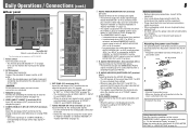
...Connections (cont.) 8 7 Rear panel 1 2 Security slot Attach a security wire to use these terminals, set "SYNC INPUT SEL." The illustration of the monitor is selected for the DVI-D signal compatible with a sampling frequency of equipment. is not displayed correctly, change the setting of the input selected last time...; The terminals accept also EMBEDDED AUDIO signals including up to AUDIO ASSIGN (IN 1 or IN 2) terminals when "SDI-1" or "SDI-2" is of DT-V24L3D. 1 Power switch Turns the power on or off all other than SDI 1 and SDI 2 is selected, the SDI signal of "DVI INPUT...
...Connections (cont.) 8 7 Rear panel 1 2 Security slot Attach a security wire to use these terminals, set "SYNC INPUT SEL." The illustration of the monitor is selected for the DVI-D signal compatible with a sampling frequency of equipment. is not displayed correctly, change the setting of the input selected last time...; The terminals accept also EMBEDDED AUDIO signals including up to AUDIO ASSIGN (IN 1 or IN 2) terminals when "SDI-1" or "SDI-2" is of DT-V24L3D. 1 Power switch Turns the power on or off all other than SDI 1 and SDI 2 is selected, the SDI signal of "DVI INPUT...
Instruction Manual
Page 9
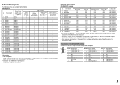
...-interlace Non-interlace Non-interlace Non-interlace Non-interlace Non-interlace Non-interlace Non-interlace Non-interlace Non-interlace Non-interlace *4 For DT-V20L3D: When No. 9, 10, 12 or 14 signals come in, thin lines will become obscured because their signal resolution is...;*3 √ √ DVI-D (HDCP) (Digital component/ digital RGB) 3 √: Acceptable -: Not acceptable *1 Analog component/analog RGB signals are available for this monitor. Input signal 9 T.M.D.S Data 1- 10 T.M.D.S Data 1+ 11 T.M.D.S Data 1 shield 12 NC 13 NC 14 +5 V Power 15 GND 16 Hot Plug Detect Pin No.
...-interlace Non-interlace Non-interlace Non-interlace Non-interlace Non-interlace Non-interlace Non-interlace Non-interlace Non-interlace Non-interlace *4 For DT-V20L3D: When No. 9, 10, 12 or 14 signals come in, thin lines will become obscured because their signal resolution is...;*3 √ √ DVI-D (HDCP) (Digital component/ digital RGB) 3 √: Acceptable -: Not acceptable *1 Analog component/analog RGB signals are available for this monitor. Input signal 9 T.M.D.S Data 1- 10 T.M.D.S Data 1+ 11 T.M.D.S Data 1 shield 12 NC 13 NC 14 +5 V Power 15 GND 16 Hot Plug Detect Pin No.
Instruction Manual
Page 10
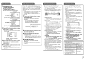
...the picture is compatible with "AUTO." • DVI-D input of moving pictures which enables you to LCD. DVI INPUT SEL. Setting value: COMPO. (component), RGB Selects the signal type you want to use... controlled by the MAKE system do Setting value MOVING PICTURE*1 Reduce the lag of the monitor is not displayed correctly with HDCP. NORMAL, CINEMA, FIELD sub menu Display the sub...Adjust the clearness of the outlines of the luminance signal compensated in "PICTURE FUNCTION." *1 DT-V24L3D only *2 Memorized for each operation. • The menu automatically disappears in to the...
...the picture is compatible with "AUTO." • DVI-D input of moving pictures which enables you to LCD. DVI INPUT SEL. Setting value: COMPO. (component), RGB Selects the signal type you want to use... controlled by the MAKE system do Setting value MOVING PICTURE*1 Reduce the lag of the monitor is not displayed correctly with HDCP. NORMAL, CINEMA, FIELD sub menu Display the sub...Adjust the clearness of the outlines of the luminance signal compensated in "PICTURE FUNCTION." *1 DT-V24L3D only *2 Memorized for each operation. • The menu automatically disappears in to the...

Instruction Manual
Page 13
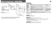
... buttons on the front panel or the menu is performed, or when the signal format changes. WAVE FORM SETTING*1 Settings for the wave form monitor Item To do Select the screen status when no filter), LOWPASS GAIN Adjust the gain level for the incoming wave form -10 - +10 ...power save mode), GRAY B. (gray screen) 30sec., 5min., 15min. OVER LEVEL Select the over the value set to make the ON, OFF wave form monitor indication go off the back light. *2 Memorized for each operation. SYNC FUNCTION Settings for the synchronization with signals Item NO SYNC ACTION DELAY TIME SYNC...
... buttons on the front panel or the menu is performed, or when the signal format changes. WAVE FORM SETTING*1 Settings for the wave form monitor Item To do Select the screen status when no filter), LOWPASS GAIN Adjust the gain level for the incoming wave form -10 - +10 ...power save mode), GRAY B. (gray screen) 30sec., 5min., 15min. OVER LEVEL Select the over the value set to make the ON, OFF wave form monitor indication go off the back light. *2 Memorized for each operation. SYNC FUNCTION Settings for the synchronization with signals Item NO SYNC ACTION DELAY TIME SYNC...
Instruction Manual
Page 14
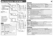
... picture size into the pixel numbers of the analog component signal B75 (compliant with BetacamVTR 0% set -up signal) Select the level of the monitor display. Select the set-up level of the input NTSC signal. 00 (compliant with 0% set-up (480i and 576i only). while viewing ...the signals. Adjust the standard level for each signal format. MIN - 000 - LOWER2: Displays the current setting at the upper part of the monitor display. 14 FUNCTION SETTING Setting for the input video signal. OFF: Fit the vertical picture size into that of the screen. LOWER1: Displays ...
... picture size into the pixel numbers of the analog component signal B75 (compliant with BetacamVTR 0% set -up signal) Select the level of the monitor display. Select the set-up level of the input NTSC signal. 00 (compliant with 0% set-up (480i and 576i only). while viewing ...the signals. Adjust the standard level for each signal format. MIN - 000 - LOWER2: Displays the current setting at the upper part of the monitor display. 14 FUNCTION SETTING Setting for the input video signal. OFF: Fit the vertical picture size into that of the screen. LOWER1: Displays ...
Instruction Manual
Page 15
... done by using the RS-232C system. ☞ "NOTE" Select if the status of the current input and the setting of the monitor Item POSITION SOURCE ID CHARACTER SET.*1 STATUS DISPLAY CRC ERROR SUB HOUR METER MODEL VERSION HOUR METER To do Setting value Select the position to...; Each time you like (10 characters at maximum). 6 Press MENU button to show the information display (☞ "On the Information Display" on standby) the monitor - Display the total hours of the MAKE/ TRIGGER terminal. • Assign a function to each video source. 1 Change the input to one that you try...
... done by using the RS-232C system. ☞ "NOTE" Select if the status of the current input and the setting of the monitor Item POSITION SOURCE ID CHARACTER SET.*1 STATUS DISPLAY CRC ERROR SUB HOUR METER MODEL VERSION HOUR METER To do Setting value Select the position to...; Each time you like (10 characters at maximum). 6 Press MENU button to show the information display (☞ "On the Information Display" on standby) the monitor - Display the total hours of the MAKE/ TRIGGER terminal. • Assign a function to each video source. 1 Change the input to one that you try...

Instruction Manual
Page 16
...the serial communication (☞ page 18). RS-485 OUT RS-485 RS-485 IN OUT External Control 16 7 About the external control This monitor has three external control terminals. • MAKE/TRIGGER terminal (RJ-45): The following items of this unit "SERIAL TYPE" setting "PARALLEL ...TYPE" setting - Consult your dealer if you need it . (2) TRIGGER (trigger) system: Controls the monitor by a personal computer or dedicated controller*2. • For the details, see page 18. You can use the external control even when "CONTROL LOCK...
...the serial communication (☞ page 18). RS-485 OUT RS-485 RS-485 IN OUT External Control 16 7 About the external control This monitor has three external control terminals. • MAKE/TRIGGER terminal (RJ-45): The following items of this unit "SERIAL TYPE" setting "PARALLEL ...TYPE" setting - Consult your dealer if you need it . (2) TRIGGER (trigger) system: Controls the monitor by a personal computer or dedicated controller*2. • For the details, see page 18. You can use the external control even when "CONTROL LOCK...
Instruction Manual
Page 17
...Non-"R-" items "R-" items 4:3 16:9 Off On ☞ "On the Status Display" on page 7). Controls whether displaying/hiding the wave form monitor (This function cannot be controlled with the MAKE system.). *7 While controlling with the MAKE system, the screen is switched. *6 Must be controlled...terminals must be controlled by the MAKE system. When the "TRIGGER" system is selected: Operate each function by pulse control, that the monitor can assign a function to each function by short-circuiting the corresponding pin terminal to different pin terminals. • The TRIGGER system ...
...Non-"R-" items "R-" items 4:3 16:9 Off On ☞ "On the Status Display" on page 7). Controls whether displaying/hiding the wave form monitor (This function cannot be controlled with the MAKE system.). *7 While controlling with the MAKE system, the screen is switched. *6 Must be controlled...terminals must be controlled by the MAKE system. When the "TRIGGER" system is selected: Operate each function by pulse control, that the monitor can assign a function to each function by short-circuiting the corresponding pin terminal to different pin terminals. • The TRIGGER system ...

Instruction Manual
Page 18
...8 CTS 9 NC • The 7th terminal and the 8th terminal are connected. "@": Status returns from the monitor • To start communication, send the connection command from the personal computer etc. • To terminate the ...(@00BOKCr) PC, etc. 3Selecting "SDI 1" input (!00BINACr) 4Monitor's status (@00BOKCr) 5Terminating the communication: termination command (!00BCN0Cr) 6Monitor's status (@00BOKCr) Monitor No. "?": Reference commands from the personal computer etc. The initial setting of the external control specification. Commands Functions 1 ! * **1 B C N 1...
...8 CTS 9 NC • The 7th terminal and the 8th terminal are connected. "@": Status returns from the monitor • To start communication, send the connection command from the personal computer etc. • To terminate the ...(@00BOKCr) PC, etc. 3Selecting "SDI 1" input (!00BINACr) 4Monitor's status (@00BOKCr) 5Terminating the communication: termination command (!00BCN0Cr) 6Monitor's status (@00BOKCr) Monitor No. "?": Reference commands from the personal computer etc. The initial setting of the external control specification. Commands Functions 1 ! * **1 B C N 1...
Instruction Manual
Page 19
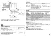
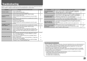
...on the menu. Though the remaining picture will disappear after the picture has changed. The LCD display is set correctly. • Adjust each picture adjustment knob on the monitor. • Adjust the picture size (H SIZE/V SIZE) or position (H POSITION/V POSITION...- 7, 9 6 8 - 6, 14 6 14 14 Symptom The picture becomes blurred. however, be aware that it may be displayed fully in the SET-UP MENU. The monitor emits a mechanical noise. 19 Probable cause and corrective action • Adjust the picture contrast or brightness by using the INPUT SELECT buttons. • Connect the...
...on the menu. Though the remaining picture will disappear after the picture has changed. The LCD display is set correctly. • Adjust each picture adjustment knob on the monitor. • Adjust the picture size (H SIZE/V SIZE) or position (H POSITION/V POSITION...- 7, 9 6 8 - 6, 14 6 14 14 Symptom The picture becomes blurred. however, be aware that it may be displayed fully in the SET-UP MENU. The monitor emits a mechanical noise. 19 Probable cause and corrective action • Adjust the picture contrast or brightness by using the INPUT SELECT buttons. • Connect the...
Instruction Manual
Page 20
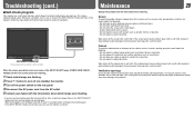
...a hard object. • Avoid condensation on the rear panel. 4 Disconnect the AC power cord from the wall outlet before turning on the monitor again. This makes troubleshooting easier. If the cabinet gets heavily stained, wipe it with a soft cloth soaked in water-diluted neutral detergent and wrung...its paint's peeling away, be careful about the following : • Do not wipe the cabinet using any rubber or plastic in appearance of DT-V24L3D. Screen To avoid irreparable change in contact for a long time. • Do not wipe the cabinet forcefully. Cabinet To avoid the ...
...a hard object. • Avoid condensation on the rear panel. 4 Disconnect the AC power cord from the wall outlet before turning on the monitor again. This makes troubleshooting easier. If the cabinet gets heavily stained, wipe it with a soft cloth soaked in water-diluted neutral detergent and wrung...its paint's peeling away, be careful about the following : • Do not wipe the cabinet using any rubber or plastic in appearance of DT-V24L3D. Screen To avoid irreparable change in contact for a long time. • Do not wipe the cabinet forcefully. Cabinet To avoid the ...
Instruction Manual
Page 21
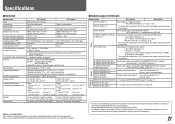
... and illustrations are shown by being emphasized, omitted or composed, and may be slightly different from sources other than JVC or JVC-authorized dealers. 7 Input/output terminals Model name DT-V24L3D DT-V20L3D VIDEO (INPUT 1) Input/output of composite signal: 1 line, BNC connector x 2, 1 V(p-p), 75 &#... format Format Audio output Operating conditions Power requirements Rated current External dimensions (excluding protruding parts) Weight Accessories DT-V24L3D DT-V20L3D Multi format LCD monitor Type 24 wide format Type 20 wide format 16:10 24˝ wide, active matrix TFT 20&#...
... and illustrations are shown by being emphasized, omitted or composed, and may be slightly different from sources other than JVC or JVC-authorized dealers. 7 Input/output terminals Model name DT-V24L3D DT-V20L3D VIDEO (INPUT 1) Input/output of composite signal: 1 line, BNC connector x 2, 1 V(p-p), 75 &#... format Format Audio output Operating conditions Power requirements Rated current External dimensions (excluding protruding parts) Weight Accessories DT-V24L3D DT-V20L3D Multi format LCD monitor Type 24 wide format Type 20 wide format 16:10 24˝ wide, active matrix TFT 20&#...

Instruction Manual
Page 24
DT-V24L3D/DT-V20L3D MULTI FORMAT LCD MONITOR © 2008 Victor Company of Japan, Limited 0908TKH-MW-MT
DT-V24L3D/DT-V20L3D MULTI FORMAT LCD MONITOR © 2008 Victor Company of Japan, Limited 0908TKH-MW-MT

