Instruction Manual
Page 1
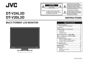
DT-V24L3D DT-V20L3D MULTI FORMAT LCD MONITOR The illustration of the monitor is intended to alert the user to persons. Refer servicing to constitute a risk of electric shock. INSTRUCTIONS Table of DT-V24L3D. Do not remove cover (or back). The lightning flash with arrowhead symbol, within an equilateral triangle is intended to alert the user...
DT-V24L3D DT-V20L3D MULTI FORMAT LCD MONITOR The illustration of the monitor is intended to alert the user to persons. Refer servicing to constitute a risk of electric shock. INSTRUCTIONS Table of DT-V24L3D. Do not remove cover (or back). The lightning flash with arrowhead symbol, within an equilateral triangle is intended to alert the user...
Instruction Manual
Page 4
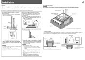
... attachment screws. CAUTION • When lifting up until it on the left and right sides of DT-V24L3D. The illustrations of the monitor are of DT-V24L3D. • To place the monitor as illustrated below ), then lift the stand up the stand when the stand plate is of the... stand. Then fix the stand firmly with the LCD panel facing down to prevent the LCD panel from about 6° upward to the lower position of DT-V24L3D. Monitor The illustration of the monitor is attached to about 6° downward. • When the monitor is of the stand body. Installation 4 CAUTION...
... attachment screws. CAUTION • When lifting up until it on the left and right sides of DT-V24L3D. The illustrations of the monitor are of DT-V24L3D. • To place the monitor as illustrated below ), then lift the stand up the stand when the stand plate is of the... stand. Then fix the stand firmly with the LCD panel facing down to prevent the LCD panel from about 6° upward to the lower position of DT-V24L3D. Monitor The illustration of the monitor is attached to about 6° downward. • When the monitor is of the stand body. Installation 4 CAUTION...
Instruction Manual
Page 5
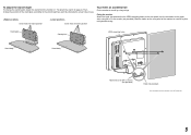
Screw holes for higher position Screw holes for lower position To prevent an accidental fall Fix the monitor to a wall or a pillar using strings. Bind the hooks on the rear panel of the monitor to a wall by choosing the screw holes to the VESA mounting holes on the rear panel (use . ...plate VESA mounting holes Stand body Stand body Hook and screw (M4 x 10 mm) (not provided) Hook (not provided) The illustration of the monitor is of DT-V24L3D. 5 To adjust the stand height To change the position of the stand plate according to the stand height you want by using durable...
Screw holes for higher position Screw holes for lower position To prevent an accidental fall Fix the monitor to a wall or a pillar using strings. Bind the hooks on the rear panel of the monitor to a wall by choosing the screw holes to the VESA mounting holes on the rear panel (use . ...plate VESA mounting holes Stand body Stand body Hook and screw (M4 x 10 mm) (not provided) Hook (not provided) The illustration of the monitor is of DT-V24L3D. 5 To adjust the stand height To change the position of the stand plate according to the stand height you want by using durable...
Instruction Manual
Page 6
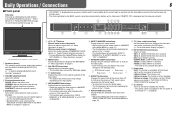
... completely off (the Power switch on the rear panel is turned off (on standby) the monitor. • The power switch is of DT-V24L3D. 1 Speakers (stereo) The speakers emit the same audio signal emitted from 4:3 to 16:9 when the picture of 16:9 aspect ratio is squeezed into 4:3 format ...; This function works only when displaying the picture in 16:9 aspect ratio. • This function does not work when displaying the picture in Green: The monitor is on. AUDIO HD/SD SDI (IN 1) terminal SDI 2: E. SAVE (power save) mode (☞ "NO SYNC ACTION" in "WAVE FORM SETTING" of the MAIN MENU...
... completely off (the Power switch on the rear panel is turned off (on standby) the monitor. • The power switch is of DT-V24L3D. 1 Speakers (stereo) The speakers emit the same audio signal emitted from 4:3 to 16:9 when the picture of 16:9 aspect ratio is squeezed into 4:3 format ...; This function works only when displaying the picture in 16:9 aspect ratio. • This function does not work when displaying the picture in Green: The monitor is on. AUDIO HD/SD SDI (IN 1) terminal SDI 2: E. SAVE (power save) mode (☞ "NO SYNC ACTION" in "WAVE FORM SETTING" of the MAIN MENU...
Instruction Manual
Page 7
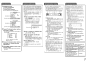
...the input - on page 12). 1 Press or button when a menu is displayed while signals come in from the speakers (L/R) and the AUDIO ASSIGN (MONITOR OUT) (OUT1(L)/OUT2(R)) terminals, when EMBEDDED AUDIO signals come in "AUDIO SETTING" on page 10 3 Displayed when "SYNC INPUT SEL." Audio channel ...is activated. ☞ " 4 MUTING button" on page 6 On the signal format The following cases: - On the Status Display If you turn on the monitor • When "STATUS DISPLAY" is set to "ON," the signal format will remain displayed 3 seconds after the previous operation. Ex.: When "MARKER" in ...
...the input - on page 12). 1 Press or button when a menu is displayed while signals come in from the speakers (L/R) and the AUDIO ASSIGN (MONITOR OUT) (OUT1(L)/OUT2(R)) terminals, when EMBEDDED AUDIO signals come in "AUDIO SETTING" on page 10 3 Displayed when "SYNC INPUT SEL." Audio channel ...is activated. ☞ " 4 MUTING button" on page 6 On the signal format The following cases: - On the Status Display If you turn on the monitor • When "STATUS DISPLAY" is set to "ON," the signal format will remain displayed 3 seconds after the previous operation. Ex.: When "MARKER" in ...
Instruction Manual
Page 8
... not be pulled out after the cover is selected, the SDI signal of DT-V24L3D. 1 Power switch Turns the power on or off. • You need to press button (☞ u on page 6) to use the monitor after turning on page 7) Make the setting for the external composite sync (... ASSIGN (IN 1/IN 2) terminals (pin jack) Input terminals for "AUDIO1 ASSIGN." or "AUDIO2 ASSIGN." (☞ "AUDIO SETTING" on page 12). 8 AUDIO ASSIGN (MONITOR OUT) terminals (pin jack) Output terminals for the analog audio signal. • The terminals output the audio signal through AUDIO ASSIGN (IN 1 or IN 2) terminals...
... not be pulled out after the cover is selected, the SDI signal of DT-V24L3D. 1 Power switch Turns the power on or off. • You need to press button (☞ u on page 6) to use the monitor after turning on page 7) Make the setting for the external composite sync (... ASSIGN (IN 1/IN 2) terminals (pin jack) Input terminals for "AUDIO1 ASSIGN." or "AUDIO2 ASSIGN." (☞ "AUDIO SETTING" on page 12). 8 AUDIO ASSIGN (MONITOR OUT) terminals (pin jack) Output terminals for the analog audio signal. • The terminals output the audio signal through AUDIO ASSIGN (IN 1 or IN 2) terminals...
Instruction Manual
Page 9
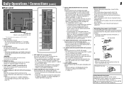
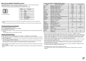
... √*3 √ √ DVI-D (HDCP) (Digital component/ digital RGB) 3 √: Acceptable -: Not acceptable *1 Analog component/analog RGB signals are available for this monitor. Input signal 17 T.M.D.S Data 0- 18 T.M.D.S Data 0+ 19 T.M.D.S Data 0 shield 20 NC 21 NC 22 T.M.D.S Clock shield 23 T.M.D.S Clock+ 24 T.M.D.S Clock- 9 Pin ...interlace Non-interlace Non-interlace Non-interlace Non-interlace Non-interlace Non-interlace Non-interlace Non-interlace Non-interlace *4 For DT-V20L3D: When No. 9, 10, 12 or 14 signals come in, thin lines will become obscured because their ...
... √*3 √ √ DVI-D (HDCP) (Digital component/ digital RGB) 3 √: Acceptable -: Not acceptable *1 Analog component/analog RGB signals are available for this monitor. Input signal 17 T.M.D.S Data 0- 18 T.M.D.S Data 0+ 19 T.M.D.S Data 0 shield 20 NC 21 NC 22 T.M.D.S Clock shield 23 T.M.D.S Clock+ 24 T.M.D.S Clock- 9 Pin ...interlace Non-interlace Non-interlace Non-interlace Non-interlace Non-interlace Non-interlace Non-interlace Non-interlace Non-interlace *4 For DT-V20L3D: When No. 9, 10, 12 or 14 signals come in, thin lines will become obscured because their ...
Instruction Manual
Page 10
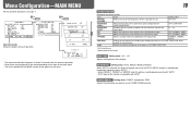
... when the picture is not displayed correctly with "AUTO." • DVI-D input of the monitor is compatible with HDCP. reset Restore the default settings for all the items in "PICTURE FUNCTION." *1 DT-V24L3D only *2 Memorized for COMPO./RGB terminals. Setting value: AUTO, MODE1, MODE2, MODE3 When... "AUTO" is peculiar to LCD. Menu Configuration-MAIN MENU For the operation procedure, see page 7. NORMAL, ...
... when the picture is not displayed correctly with "AUTO." • DVI-D input of the monitor is compatible with HDCP. reset Restore the default settings for all the items in "PICTURE FUNCTION." *1 DT-V24L3D only *2 Memorized for COMPO./RGB terminals. Setting value: AUTO, MODE1, MODE2, MODE3 When... "AUTO" is peculiar to LCD. Menu Configuration-MAIN MENU For the operation procedure, see page 7. NORMAL, ...

Instruction Manual
Page 13
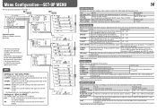
...; "NOTE" signals. Video signal Start End 13 OVER LEVEL Select the over the value set to change the OFF, ON color of the wave form monitor. 1 (lower right), 2 (lower left), 3 (upper left), 4 (upper right) FILTER Activates/deactivates the low-pass filter for the incoming wave form -10 ... VIDEO1, VIDEO2 and COMPO./RGB input. Operation guide Shows the buttons for each operation. WAVE FORM SETTING*1 Settings for the wave form monitor Item To do Select the screen status when no filter), LOWPASS GAIN Adjust the gain level for the incoming wave form data. LEVEL...
...; "NOTE" signals. Video signal Start End 13 OVER LEVEL Select the over the value set to change the OFF, ON color of the wave form monitor. 1 (lower right), 2 (lower left), 3 (upper left), 4 (upper right) FILTER Activates/deactivates the low-pass filter for the incoming wave form -10 ... VIDEO1, VIDEO2 and COMPO./RGB input. Operation guide Shows the buttons for each operation. WAVE FORM SETTING*1 Settings for the wave form monitor Item To do Select the screen status when no filter), LOWPASS GAIN Adjust the gain level for the incoming wave form data. LEVEL...
Instruction Manual
Page 14
... Setting value Adjust the horizontal picture size. MIN - 000 - OFF: Fit the vertical picture size into that of the monitor display. 14 FUNCTION SETTING Setting for some items. Settings of the monitor display. ON: Fit the vertical picture size into the pixel numbers of "SD4:3 LARGE" The setting values and features are...
... Setting value Adjust the horizontal picture size. MIN - 000 - OFF: Fit the vertical picture size into that of the monitor display. 14 FUNCTION SETTING Setting for some items. Settings of the monitor display. ON: Fit the vertical picture size into the pixel numbers of "SD4:3 LARGE" The setting values and features are...
Instruction Manual
Page 15
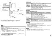
...on the menu. You cannot reset this item. *1 Memorized for each pin terminal by the MAKE/ TRIGGER system" on !" Operating the monitor by an external control If you cannot change the assignment of these functions.) Setting value RS232C, RS485 MAKE, TRIGGER, SET ☞ "Functions...space. • The characters entered before moving the arrow are assigned for "PIN6" - This item is activated. - Display the version of the monitor. "PIN8" and you try other operations, " Control lock on page 17 INFORMATION Settings for the information display of the MAKE/ TRIGGER terminal. &#...
...on the menu. You cannot reset this item. *1 Memorized for each pin terminal by the MAKE/ TRIGGER system" on !" Operating the monitor by an external control If you cannot change the assignment of these functions.) Setting value RS232C, RS485 MAKE, TRIGGER, SET ☞ "Functions...space. • The characters entered before moving the arrow are assigned for "PIN6" - This item is activated. - Display the version of the monitor. "PIN8" and you try other operations, " Control lock on page 17 INFORMATION Settings for the information display of the MAKE/ TRIGGER terminal. &#...

Instruction Manual
Page 16
... the equipment is actually connected to "ON" (☞ page 15). • When the monitor is off (on the monitor) are available. (1) MAKE (make contact) system: Controls the monitor by short-circuiting the corresponding pin terminal to the GND pin terminal, or disconnecting (opening) ...it . Control priority is not commercially available. MAKE > TRIGGER = serial communication = buttons and menu on the monitor • You can control the monitor by sending the pulse signal instantaneously to the external control terminal and control system (☞ "SERIAL TYPE", "PARALLEL TYPE...
... the equipment is actually connected to "ON" (☞ page 15). • When the monitor is off (on the monitor) are available. (1) MAKE (make contact) system: Controls the monitor by short-circuiting the corresponding pin terminal to the GND pin terminal, or disconnecting (opening) ...it . Control priority is not commercially available. MAKE > TRIGGER = serial communication = buttons and menu on the monitor • You can control the monitor by sending the pulse signal instantaneously to the external control terminal and control system (☞ "SERIAL TYPE", "PARALLEL TYPE...
Instruction Manual
Page 17
... to be controlled by the external control. 3 When the "MAKE" system is selected: Operate each function by pulse control, that the monitor can be controlled TALLY SEL Selects the color of short-circuiting. *5 While controlling with MAKE system, only one pin terminal must be short...cannot assign the same function to "OFF," the level meter is switched between normal screen (opening ). Controls whether displaying/hiding the wave form monitor (This function cannot be controlled with the MAKE system, the screen is a female terminal. While controlling with the TRIGGER system, the screen ...
... to be controlled by the external control. 3 When the "MAKE" system is selected: Operate each function by pulse control, that the monitor can be controlled TALLY SEL Selects the color of short-circuiting. *5 While controlling with MAKE system, only one pin terminal must be short...cannot assign the same function to "OFF," the level meter is switched between normal screen (opening ). Controls whether displaying/hiding the wave form monitor (This function cannot be controlled with the MAKE system, the screen is a female terminal. While controlling with the TRIGGER system, the screen ...

Instruction Manual
Page 18
... TXD - RXD + RXD + NC NC NC NC RXD - NC NC GND GND Pin No. of the monitor's ID is a female terminal. All commands consist of communication procedures 1Starting the communication: connection command (!00BCN1Cr) 2Monitor's...the ID 6 ! * **1 B I S P Cr Displays the status*3 22 ! * **1 B A M U T E x x*2 Cr Turns muting on/off (on standby). *1 Enter the monitor's ID for " **." "?": Reference commands from the personal computer, etc. TXD - Input terminal Cable Terminal specification Communication specifications RS-485 RS-232C A straight LAN cable A straight...
... TXD - RXD + RXD + NC NC NC NC RXD - NC NC GND GND Pin No. of the monitor's ID is a female terminal. All commands consist of communication procedures 1Starting the communication: connection command (!00BCN1Cr) 2Monitor's...the ID 6 ! * **1 B I S P Cr Displays the status*3 22 ! * **1 B A M U T E x x*2 Cr Turns muting on/off (on standby). *1 Enter the monitor's ID for " **." "?": Reference commands from the personal computer, etc. TXD - Input terminal Cable Terminal specification Communication specifications RS-485 RS-232C A straight LAN cable A straight...
Instruction Manual
Page 19
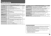
...Symptom The picture becomes blurred. ADJ." Disable the external control. This is due to the characteristics of LCD displays, and not a problem. The monitor emits a cracking noise. - Buttons on the monitor do not appear on the screen after a while, there may be a case that a few pixels... signal cable firmly. • Turn on the power of the connected component and set correctly. • Adjust each picture adjustment knob on the monitor. • Adjust the picture size (H SIZE/V SIZE) or position (H POSITION/V POSITION) of 1:1 or ASPECT buttons is appropriate. • ...
...Symptom The picture becomes blurred. ADJ." Disable the external control. This is due to the characteristics of LCD displays, and not a problem. The monitor emits a cracking noise. - Buttons on the monitor do not appear on the screen after a while, there may be a case that a few pixels... signal cable firmly. • Turn on the power of the connected component and set correctly. • Adjust each picture adjustment knob on the monitor. • Adjust the picture size (H SIZE/V SIZE) or position (H POSITION/V POSITION) of 1:1 or ASPECT buttons is appropriate. • ...
Instruction Manual
Page 20
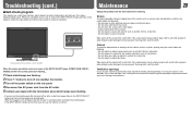
... dust around the intakes may be careful about which lamps are flashing. 2 Press button to detect malfunctions and alert you turn on the monitor soon after a short-term power failure), the INPUT SELECT lamps may flash and no image may prevent proper temperature control and cause damage...Use a vacuum cleaner to the product. Leaving the dust around the intakes (all the openings). Whenever a problem occurs, one or some of DT-V24L3D. Maintenance 20 Unplug this happens, turn off power and wait at least 10 seconds before cleaning. If the screen gets heavily stained, wipe ...
... dust around the intakes may be careful about which lamps are flashing. 2 Press button to detect malfunctions and alert you turn on the monitor soon after a short-term power failure), the INPUT SELECT lamps may flash and no image may prevent proper temperature control and cause damage...Use a vacuum cleaner to the product. Leaving the dust around the intakes (all the openings). Whenever a problem occurs, one or some of DT-V24L3D. Maintenance 20 Unplug this happens, turn off power and wait at least 10 seconds before cleaning. If the screen gets heavily stained, wipe ...
Instruction Manual
Page 21
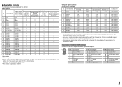
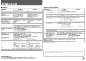
...video signal format Format Audio output Operating conditions Power requirements Rated current External dimensions (excluding protruding parts) Weight Accessories DT-V24L3D DT-V20L3D Multi format LCD monitor Type 24 wide format Type 20 wide format 16:10 24˝ wide, active matrix TFT 20˝... are shown by being emphasized, omitted or composed, and may be slightly different from sources other than JVC or JVC-authorized dealers. 7 Input/output terminals Model name DT-V24L3D DT-V20L3D VIDEO (INPUT 1) Input/output of their respective companies. 21 DVI-D (HDCP) DVI-D signal ...
...video signal format Format Audio output Operating conditions Power requirements Rated current External dimensions (excluding protruding parts) Weight Accessories DT-V24L3D DT-V20L3D Multi format LCD monitor Type 24 wide format Type 20 wide format 16:10 24˝ wide, active matrix TFT 20˝... are shown by being emphasized, omitted or composed, and may be slightly different from sources other than JVC or JVC-authorized dealers. 7 Input/output terminals Model name DT-V24L3D DT-V20L3D VIDEO (INPUT 1) Input/output of their respective companies. 21 DVI-D (HDCP) DVI-D signal ...
Instruction Manual
Page 24
DT-V24L3D/DT-V20L3D MULTI FORMAT LCD MONITOR © 2008 Victor Company of Japan, Limited 0908TKH-MW-MT
DT-V24L3D/DT-V20L3D MULTI FORMAT LCD MONITOR © 2008 Victor Company of Japan, Limited 0908TKH-MW-MT

