Instructions
Page 1
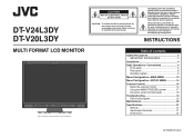
... intended to alert the user to the presence of uninsulated "dangerous voltage" within an equilateral triangle is of DT-V24L3DY. Do not remove cover (or back). DT-V24L3DY DT-V20L3DY MULTI FORMAT LCD MONITOR The illustration of the monitor is intended to alert the user to the presence of important operating and maintenance (servicing) instructions in...
... intended to alert the user to the presence of uninsulated "dangerous voltage" within an equilateral triangle is of DT-V24L3DY. Do not remove cover (or back). DT-V24L3DY DT-V20L3DY MULTI FORMAT LCD MONITOR The illustration of the monitor is intended to alert the user to the presence of important operating and maintenance (servicing) instructions in...
Instructions
Page 4
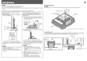
... Screw (silver) About 148° 2 Attach the removed screws and place the monitor as illustrated below . Monitor The illustration of the monitor is of DT-V24L3DY. Guide holes Guidelines The illustration of the monitor is of DT-V24L3DY. • You can tilt the monitor from about 148°); Installation 4 CAUTION • Do not rest your arm on...
... Screw (silver) About 148° 2 Attach the removed screws and place the monitor as illustrated below . Monitor The illustration of the monitor is of DT-V24L3DY. Guide holes Guidelines The illustration of the monitor is of DT-V24L3DY. • You can tilt the monitor from about 148°); Installation 4 CAUTION • Do not rest your arm on...

Instructions
Page 5
... Stand plate VESA mounting holes Stand body Stand body Hook and screw (M4 x 10 mm) (not provided) Hook (not provided) The illustration of the monitor is of DT-V24L3DY. 5 Screw holes for higher position Screw holes for lower position To prevent an accidental fall Fix the... monitor to a wall by choosing the screw holes to the VESA mounting holes on the upper side) using durable string. Fixing the monitor Attach the hook (not provided) to use the two...
... Stand plate VESA mounting holes Stand body Stand body Hook and screw (M4 x 10 mm) (not provided) Hook (not provided) The illustration of the monitor is of DT-V24L3DY. 5 Screw holes for higher position Screw holes for lower position To prevent an accidental fall Fix the... monitor to a wall by choosing the screw holes to the VESA mounting holes on the upper side) using durable string. Fixing the monitor Attach the hook (not provided) to use the two...
Instructions
Page 6
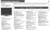
...6 7 Front panel Tally lamp This lamp is controlled by the buttons on standby). Flashes in orange: The monitor is in "SYNC FUNCTION" on page 13). The illustration of the monitor is of DT-V24L3DY. 1 Speakers (stereo) The speakers emit the same audio signal emitted from 4:3 to 16:9 when the... Changes the aspect ratio of the MAIN MENU (☞ page 13). • The closed caption (☞ page 13) disappears when the wave form monitor is on page 7) t INPUT SELECT buttons/lamps Selects an input. r T.C. (time code) button/lamp Activates/deactivates the display of the time data...
...6 7 Front panel Tally lamp This lamp is controlled by the buttons on standby). Flashes in orange: The monitor is in "SYNC FUNCTION" on page 13). The illustration of the monitor is of DT-V24L3DY. 1 Speakers (stereo) The speakers emit the same audio signal emitted from 4:3 to 16:9 when the... Changes the aspect ratio of the MAIN MENU (☞ page 13). • The closed caption (☞ page 13) disappears when the wave form monitor is on page 7) t INPUT SELECT buttons/lamps Selects an input. r T.C. (time code) button/lamp Activates/deactivates the display of the time data...
Instructions
Page 7
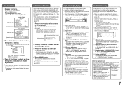
...hide the status in the following messages appear depending on page 13 4 Setting of input signals and their conditions. On the Information Display The monitor displays the information below and "Available signals" on page 9. 3 Source name assigned in "CHARACTER SET." • Displayed when "SOURCE ID...end of with a button. • Select the position of the information display (☞ "POSITION" in from the speakers (L/R) and the AUDIO ASSIGN (MONITOR OUT) (OUT1(L)/OUT2(R)) terminals, when EMBEDDED AUDIO signals come in "AUDIO SETTING" on page 12). 1 Press or button when a menu is not...
...hide the status in the following messages appear depending on page 13 4 Setting of input signals and their conditions. On the Information Display The monitor displays the information below and "Available signals" on page 9. 3 Source name assigned in "CHARACTER SET." • Displayed when "SOURCE ID...end of with a button. • Select the position of the information display (☞ "POSITION" in from the speakers (L/R) and the AUDIO ASSIGN (MONITOR OUT) (OUT1(L)/OUT2(R)) terminals, when EMBEDDED AUDIO signals come in "AUDIO SETTING" on page 12). 1 Press or button when a menu is not...
Instructions
Page 8
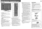
...pin jack) Input terminals for the analog audio signals. • Use this terminal. • The signals are completed. 3 REMOTE terminal Terminal for controlling the monitor by an external control. (☞ "External Control" on page 16) 4 VIDEO (INPUT 1/INPUT 2) terminals (BNC) Input (IN) and output (OUT)...the composite signals. 5 COMPO./RGB (G/Y, B/PB/B-Y, R/PR/R-Y) terminals (BNC) Input (IN) and output (OUT) terminals for "AUDIO1 ASSIGN." is of DT-V24L3DY. 1 Power switch Turns the power on or off all the equipment. • Use a cord whose plugs correctly match the terminals on page 12...
...pin jack) Input terminals for the analog audio signals. • Use this terminal. • The signals are completed. 3 REMOTE terminal Terminal for controlling the monitor by an external control. (☞ "External Control" on page 16) 4 VIDEO (INPUT 1/INPUT 2) terminals (BNC) Input (IN) and output (OUT)...the composite signals. 5 COMPO./RGB (G/Y, B/PB/B-Y, R/PR/R-Y) terminals (BNC) Input (IN) and output (OUT) terminals for "AUDIO1 ASSIGN." is of DT-V24L3DY. 1 Power switch Turns the power on or off all the equipment. • Use a cord whose plugs correctly match the terminals on page 12...
Instructions
Page 9
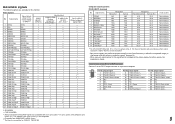
... Non-interlace Non-interlace Non-interlace Non-interlace Non-interlace Non-interlace *4 For DT-V20L3DY: When No. 9, 10, 12 or 14 signals come in, thin lines... digital RGB) 3 √*3 √: Acceptable -: Not acceptable *1 Analog component/analog RGB signals are available for this monitor. For other signals, the resolution is shown on page 21). • When a preset signal comes in the status display... 480/60i 480/60i 6 480/59.94i 480/59.94i 7 576/50i 576/50i 8 480/60p 480/60p 9 480/59.94p 480/59.94p 10 576/50p 576/50p 11 640*480/60p 640*480/60p 12 640*480/59.94p 640*480/...
... Non-interlace Non-interlace Non-interlace Non-interlace Non-interlace Non-interlace *4 For DT-V20L3DY: When No. 9, 10, 12 or 14 signals come in, thin lines... digital RGB) 3 √*3 √: Acceptable -: Not acceptable *1 Analog component/analog RGB signals are available for this monitor. For other signals, the resolution is shown on page 21). • When a preset signal comes in the status display... 480/60i 480/60i 6 480/59.94i 480/59.94i 7 576/50i 576/50i 8 480/60p 480/60p 9 480/59.94p 480/59.94p 10 576/50p 576/50p 11 640*480/60p 640*480/60p 12 640*480/59.94p 640*480/...
Instructions
Page 10
...you to adjust the items of signals come in to LCD. reset Restore the default settings for all the items in "PICTURE FUNCTION." *1 DT-V24L3DY only *2 Memorized for each operation. • The menu automatically disappears in "APERTURE LEVEL." OFF, LOW, HIGH APERTURE LEVEL*2 Compensate ... not appear on the menu. 10 PICTURE FUNCTION Setting for the picture quality Item To do Setting value MOVING PICTURE*1 Reduce the lag of the monitor is peculiar to the DVI-D (HDCP) terminal is automatically recognized. (Normally, select "AUTO.") • Select "MODE1", "MODE2" or "MODE3...
...you to adjust the items of signals come in to LCD. reset Restore the default settings for all the items in "PICTURE FUNCTION." *1 DT-V24L3DY only *2 Memorized for each operation. • The menu automatically disappears in "APERTURE LEVEL." OFF, LOW, HIGH APERTURE LEVEL*2 Compensate ... not appear on the menu. 10 PICTURE FUNCTION Setting for the picture quality Item To do Setting value MOVING PICTURE*1 Reduce the lag of the monitor is peculiar to the DVI-D (HDCP) terminal is automatically recognized. (Normally, select "AUTO.") • Select "MODE1", "MODE2" or "MODE3...

Instructions
Page 13
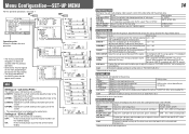
...White • The wave which goes over level for analog composite signals (NTSC and B/W60 only). • Regardless of the wave form monitor. Setting value OFF, P.SAVE (power save mode) saves more power consumption by half. FILTER GAIN OVER LEVEL MARKING LEVEL AUTO OFF Activates/...RGB input signals (analog/digital), DVI signals (digital/inputted from personal computer), 1080/60p (analog/digital), 1080/50p (analog/digital), 640 *480/60p (analog/digital). Operation guide Shows the buttons for the VIDEO1, VIDEO2 and COMPO./RGB input. Adjust the gain level for each input ...
...White • The wave which goes over level for analog composite signals (NTSC and B/W60 only). • Regardless of the wave form monitor. Setting value OFF, P.SAVE (power save mode) saves more power consumption by half. FILTER GAIN OVER LEVEL MARKING LEVEL AUTO OFF Activates/...RGB input signals (analog/digital), DVI signals (digital/inputted from personal computer), 1080/60p (analog/digital), 1080/50p (analog/digital), 640 *480/60p (analog/digital). Operation guide Shows the buttons for the VIDEO1, VIDEO2 and COMPO./RGB input. Adjust the gain level for each input ...
Instructions
Page 14
... current setting at the lower part of the screen. OFF: Fit the vertical picture size into that of the monitor display. ON: Fit the vertical picture size into the pixel numbers of the monitor display. 14 FUNCTION SETTING Setting for the phase adjusted -20 - +20 with "AUTO," select "PAL" or "NTSC." PHASE...
... current setting at the lower part of the screen. OFF: Fit the vertical picture size into that of the monitor display. ON: Fit the vertical picture size into the pixel numbers of the monitor display. 14 FUNCTION SETTING Setting for the phase adjusted -20 - +20 with "AUTO," select "PAL" or "NTSC." PHASE...

Instructions
Page 15
...On the Status Display" on page 7). This item is displayed ON, OFF on the screen (☞ "On the Information Display" on standby) the monitor - appears on page 7). is activated. - Display the hours of these functions.) Setting value RS232C, RS485 MAKE, TRIGGER, SET ☞ "Functions ...when this function is displayed on the screen (☞ "On the Information Display" on the screen. Display the version of the monitor. Operating the monitor by the MAKE/ TRIGGER system" on page 17 INFORMATION Settings for the information display of muting are assigned for "PIN6" -...
...On the Status Display" on page 7). This item is displayed ON, OFF on the screen (☞ "On the Information Display" on standby) the monitor - appears on page 7). is activated. - Display the hours of these functions.) Setting value RS232C, RS485 MAKE, TRIGGER, SET ☞ "Functions ...when this function is displayed on the screen (☞ "On the Information Display" on the screen. Display the version of the monitor. Operating the monitor by the MAKE/ TRIGGER system" on page 17 INFORMATION Settings for the information display of muting are assigned for "PIN6" -...

Instructions
Page 16
... OUT IN • For the details, see page 17. *2 The controller is off (on the monitor) are available. (1) MAKE (make contact) system: Controls the monitor by short-circuiting the corresponding pin terminal to the corresponding pin terminal. ☞ "Using the MAKE/TRIGGER... controls (starting/ terminating communication, turning on standby), external control is as follows. External Control 16 7 About the external control This monitor has three external control terminals. • MAKE/TRIGGER terminal (RJ-45): The following external control systems are available through the serial ...
... OUT IN • For the details, see page 17. *2 The controller is off (on the monitor) are available. (1) MAKE (make contact) system: Controls the monitor by short-circuiting the corresponding pin terminal to the corresponding pin terminal. ☞ "Using the MAKE/TRIGGER... controls (starting/ terminating communication, turning on standby), external control is as follows. External Control 16 7 About the external control This monitor has three external control terminals. • MAKE/TRIGGER terminal (RJ-45): The following external control systems are available through the serial ...

Instructions
Page 17
...1 second and opening the terminal (regardless of the audio channel display is switched. *6 While controlling with the MAKE system, the wave form monitor will not disappear until opening it . MUTING Muting on page 13). *7 For analog composite signals (NTSC and B/W60 only). While controlling ... Operate each pin terminal in 1:1 mode. When the "TRIGGER" system is selected: Operate each function by one by pulse control, that the monitor can be controlled by the external control. 3 When the "MAKE" system is not displayed ("NO EFFECT" appears). While controlling with the TRIGGER...
...1 second and opening the terminal (regardless of the audio channel display is switched. *6 While controlling with the MAKE system, the wave form monitor will not disappear until opening it . MUTING Muting on page 13). *7 For analog composite signals (NTSC and B/W60 only). While controlling ... Operate each pin terminal in 1:1 mode. When the "TRIGGER" system is selected: Operate each function by one by pulse control, that the monitor can be controlled by the external control. 3 When the "MAKE" system is not displayed ("NO EFFECT" appears). While controlling with the TRIGGER...

Instructions
Page 18
.../hides the ID 6 ! * **1 B I S P Cr Displays the status*3 22 ! * **1 B A M U T E x x*2 Cr Turns muting on/off (on standby). *1 Enter the monitor's ID for starting communication (connection) (No. 1), terminating communication (termination) (No. 2), and turning on the right. RXD + RXD + NC NC NC NC RXD - All commands consist... "SDI 1" input (!00BINACr) 4Monitor's status (@00BOKCr) 5Terminating the communication: termination command (!00BCN0Cr) 6Monitor's status (@00BOKCr) Monitor No. Pin No. 1 2 3 4 5 6 7 8 IN terminal signal OUT terminal signal TXD + TXD + ...
.../hides the ID 6 ! * **1 B I S P Cr Displays the status*3 22 ! * **1 B A M U T E x x*2 Cr Turns muting on/off (on standby). *1 Enter the monitor's ID for starting communication (connection) (No. 1), terminating communication (termination) (No. 2), and turning on the right. RXD + RXD + NC NC NC NC RXD - All commands consist... "SDI 1" input (!00BINACr) 4Monitor's status (@00BOKCr) 5Terminating the communication: termination command (!00BCN0Cr) 6Monitor's status (@00BOKCr) Monitor No. Pin No. 1 2 3 4 5 6 7 8 IN terminal signal OUT terminal signal TXD + TXD + ...
Instructions
Page 19
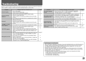
...ADJ." in "FUNCTION SETTING" of the SET-UP MENU. • Adjust the items of the solutions presented here solve the problem, unplug the monitor and consult an authorized dealer or service center. Change the input or the input signal. • The items controlled by using the INPUT SELECT ...of "WHITE BALANCE SET." Buttons on No sound "OTHERS" or "Out of "PICTURE SUB ADJ." A slight electric shock occurs when you touch the monitor. - Probable cause and corrective action • Adjust the picture contrast or brightness by the MAKE system do not appear on the panel surface are a...
...ADJ." in "FUNCTION SETTING" of the SET-UP MENU. • Adjust the items of the solutions presented here solve the problem, unplug the monitor and consult an authorized dealer or service center. Change the input or the input signal. • The items controlled by using the INPUT SELECT ...of "WHITE BALANCE SET." Buttons on No sound "OTHERS" or "Out of "PICTURE SUB ADJ." A slight electric shock occurs when you touch the monitor. - Probable cause and corrective action • Adjust the picture contrast or brightness by the MAKE system do not appear on the panel surface are a...
Instructions
Page 20
...openings Use a vacuum cleaner to the product. Leaving the dust around the intakes (all the openings). Cabinet To avoid the deterioration or damages of DT-V24L3DY. If a vacuum cleaner is of the cabinet such as its paint's peeling away, be displayed. Wipe stains off the screen with a... a soft cloth soaked in water-diluted neutral detergent and wrung well, then wipe with a soft cloth. Troubleshooting (cont.) 7 Self-check program This monitor has a self-check function, which lamps were flashing. • If you turn off power and wait at least 10 seconds before cleaning. If this...
...openings Use a vacuum cleaner to the product. Leaving the dust around the intakes (all the openings). Cabinet To avoid the deterioration or damages of DT-V24L3DY. If a vacuum cleaner is of the cabinet such as its paint's peeling away, be displayed. Wipe stains off the screen with a... a soft cloth soaked in water-diluted neutral detergent and wrung well, then wipe with a soft cloth. Troubleshooting (cont.) 7 Self-check program This monitor has a self-check function, which lamps were flashing. • If you turn off power and wait at least 10 seconds before cleaning. If this...
Instructions
Page 21
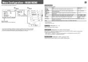
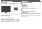
... Format Audio output Operating conditions Power requirements Rated current External dimensions (excluding protruding parts) Weight Accessories DT-V24L3DY DT-V20L3DY Multi format LCD monitor Type 24 wide format Type 20 wide format 16:10 24˝ wide, active matrix TFT ... cord holder x 1, Screw x 2 (for identification purposes only, and may be slightly different from sources other than JVC or JVC-authorized dealers. 7 Input/output terminals Model name DT-V24L3DY DT-V20L3DY VIDEO (INPUT 1) Input/output of analog component signal/analog RGB signal: 1 line, BNC connector x 6 G/Y: 1...
... Format Audio output Operating conditions Power requirements Rated current External dimensions (excluding protruding parts) Weight Accessories DT-V24L3DY DT-V20L3DY Multi format LCD monitor Type 24 wide format Type 20 wide format 16:10 24˝ wide, active matrix TFT ... cord holder x 1, Screw x 2 (for identification purposes only, and may be slightly different from sources other than JVC or JVC-authorized dealers. 7 Input/output terminals Model name DT-V24L3DY DT-V20L3DY VIDEO (INPUT 1) Input/output of analog component signal/analog RGB signal: 1 line, BNC connector x 6 G/Y: 1...

Instructions
Page 24
DT-V24L3DY/DT-V20L3DY MULTI FORMAT LCD MONITOR © 2008 Victor Company of Japan, Limited 1008TKH-MW-VP
DT-V24L3DY/DT-V20L3DY MULTI FORMAT LCD MONITOR © 2008 Victor Company of Japan, Limited 1008TKH-MW-VP

