

Instruction Manual
Page 1
... servicing to qualified service personnel. Do not remove cover (or back). INSTRUCTIONS Table of electric shock. No user serviceable parts inside. DT-V17L3D MULTI FORMAT LCD MONITOR CAUTION RISK OF ELECTRICAL SHOCK DO NOT OPEN CAUTION: To reduce the risk of Contents Safety Precautions 2 IMPORTANT SAFEGUARDS 2 Installation 4 Daily Operations / Connections...
... servicing to qualified service personnel. Do not remove cover (or back). INSTRUCTIONS Table of electric shock. No user serviceable parts inside. DT-V17L3D MULTI FORMAT LCD MONITOR CAUTION RISK OF ELECTRICAL SHOCK DO NOT OPEN CAUTION: To reduce the risk of Contents Safety Precautions 2 IMPORTANT SAFEGUARDS 2 Installation 4 Daily Operations / Connections...

Instruction Manual
Page 4
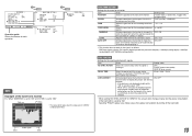
... illustration below . • You can select the stand height-higher position or lower position (☞ "To adjust the stand height" on the supplied stand. Monitor About 12° 0° About 8° Stand When the stand plate is attached to the higher position of the stand body (☞ "To adjust the... the lower position of the stand body. • When the battery is not tilted (0°), the guidelines align as follows. You can place the monitor in the moving parts. • Make sure of lifting the stand up the stand... - Guidelines 2 Attach the removed screws and place the...
... illustration below . • You can select the stand height-higher position or lower position (☞ "To adjust the stand height" on the supplied stand. Monitor About 12° 0° About 8° Stand When the stand plate is attached to the higher position of the stand body (☞ "To adjust the... the lower position of the stand body. • When the battery is not tilted (0°), the guidelines align as follows. You can place the monitor in the moving parts. • Make sure of lifting the stand up the stand... - Guidelines 2 Attach the removed screws and place the...

Instruction Manual
Page 5
... mm screws (not provided). Stand plate Screw holes for higher position Screw holes for lower position Stand plate To prevent an accidental fall Fix the monitor to a wall by choosing the screw holes to the stand height you want by using durable string. Then, change the stand height, detach the... stand from the monitor (☞ "To detach the stand" on page 4). VESA mounting holes Stand body Stand body Hook and screw (M4 x 10 mm) (not provided) Hook (not...
... mm screws (not provided). Stand plate Screw holes for higher position Screw holes for lower position Stand plate To prevent an accidental fall Fix the monitor to a wall by choosing the screw holes to the stand height you want by using durable string. Then, change the stand height, detach the... stand from the monitor (☞ "To detach the stand" on page 4). VESA mounting holes Stand body Stand body Hook and screw (M4 x 10 mm) (not provided) Hook (not...
Instruction Manual
Page 6
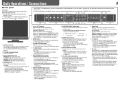
... screen w ASPECT button/lamp Changes the aspect ratio of the picture from green. When the voltage becomes lower than a certain level, the monitor automatically turns off the POWER switch and DC switch on the rear panel before replacing the battery. • The length of time that the... turns to 4:3, press the button again. • This function does not work when displaying the picture in the 1:1 mode. Lights in Green: The monitor is on the type of battery or the battery condition. CHROMA: Adjusts the picture color density. Daily Operations / Connections 6 7 Front panel Tally lamp ...
... screen w ASPECT button/lamp Changes the aspect ratio of the picture from green. When the voltage becomes lower than a certain level, the monitor automatically turns off the POWER switch and DC switch on the rear panel before replacing the battery. • The length of time that the... turns to 4:3, press the button again. • This function does not work when displaying the picture in the 1:1 mode. Lights in Green: The monitor is on the type of battery or the battery condition. CHROMA: Adjusts the picture color density. Daily Operations / Connections 6 7 Front panel Tally lamp ...
Instruction Manual
Page 7
...r T.C. (time code) button/lamp" on page 6 • When any information of range" When "COLOR SYSTEM" (☞ "FUNCTION SETTING" on the monitor • When "STATUS DISPLAY" is set to "AUTO" and the noncompliant composite video signals come in \ "OTHERS" 7 displaying the picture with higher resolution... signal comes in \ "Out of 1, 2, 3, or 4 above is displayed while signals come in from the speakers (L/R) and the AUDIO (MONITOR OUT) (OUT1(L)/ OUT2(R)) terminals, when EMBEDDED AUDIO signals come in to finish the menu operation. • Pressing MENU button repeatedly deactivates the...
...r T.C. (time code) button/lamp" on page 6 • When any information of range" When "COLOR SYSTEM" (☞ "FUNCTION SETTING" on the monitor • When "STATUS DISPLAY" is set to "AUTO" and the noncompliant composite video signals come in \ "OTHERS" 7 displaying the picture with higher resolution... signal comes in \ "Out of 1, 2, 3, or 4 above is displayed while signals come in from the speakers (L/R) and the AUDIO (MONITOR OUT) (OUT1(L)/ OUT2(R)) terminals, when EMBEDDED AUDIO signals come in to finish the menu operation. • Pressing MENU button repeatedly deactivates the...
Instruction Manual
Page 8
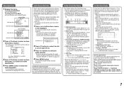
...analog component video (color difference) signals. 4 AUDIO (IN) terminals (pin jack) Input terminals for the analog audio signals. • Use this monitor and the equipment. • Plugs should be firmly inserted; q AC IN terminal AC power input connector. e Screw holes for external battery attachment Attach...u on page 6) to grasp its plug and pull it may fall off all connections are completed. 1 REMOTE terminal Terminal for controlling the monitor by using 2 screw holes. w POWER switch Turns AC power on standby. Choose the appropriate screw holes from the mount as illustrated below...
...analog component video (color difference) signals. 4 AUDIO (IN) terminals (pin jack) Input terminals for the analog audio signals. • Use this monitor and the equipment. • Plugs should be firmly inserted; q AC IN terminal AC power input connector. e Screw holes for external battery attachment Attach...u on page 6) to grasp its plug and pull it may fall off all connections are completed. 1 REMOTE terminal Terminal for controlling the monitor by using 2 screw holes. w POWER switch Turns AC power on standby. Choose the appropriate screw holes from the mount as illustrated below...
Instruction Manual
Page 9
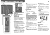
...; √ √ - - - - √ √ √ √ √ √ √*3 √*3 √ √ DVI-D (HDCP) (Digital component/ digital RGB 3 *1 Analog component signals are available for this monitor. Pin No. 7 Available signals The following signals are compatible with Y on sync signals. *2 Compatible with EMBEDDED AUDIO signals *3 The signal is recognized as 1080/60i...
...; √ √ - - - - √ √ √ √ √ √ √*3 √*3 √ √ DVI-D (HDCP) (Digital component/ digital RGB 3 *1 Analog component signals are available for this monitor. Pin No. 7 Available signals The following signals are compatible with Y on sync signals. *2 Compatible with EMBEDDED AUDIO signals *3 The signal is recognized as 1080/60i...

Instruction Manual
Page 10
... with "AUTO." • DVI-D input of signals come in "APERTURE LEVEL." Setting value: AUTO, MODE1, MODE2, MODE3 When "AUTO" is selected, the format of the monitor is compatible with HDCP. BACK LIGHT Setting value: -20 - +20 Adjusts the brightness of "PICTURE FUNCTION" while viewing the actual picture. Menu Configuration-MAIN MENU...
... with "AUTO." • DVI-D input of signals come in "APERTURE LEVEL." Setting value: AUTO, MODE1, MODE2, MODE3 When "AUTO" is selected, the format of the monitor is compatible with HDCP. BACK LIGHT Setting value: -20 - +20 Adjusts the brightness of "PICTURE FUNCTION" while viewing the actual picture. Menu Configuration-MAIN MENU...
Instruction Manual
Page 13
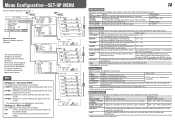
...signal is performed, or when the signal format changes. MARKING Activates/deactivates the function to change the OFF, ON color of the wave form monitor Ex.: When "MARKING" is set to display the picture (low latency function). • If the picture is not displayed steadily while ... goes over level for the luminance signal 070 -109 AUTO OFF Activates/deactivates the function to gray and the power consumption of the wave form monitor. 1 (lower right), 2 (lower left), 3 (upper left), 4 (upper right) FILTER Activates/deactivates the low-pass filter for each operation. Setting ...
...signal is performed, or when the signal format changes. MARKING Activates/deactivates the function to change the OFF, ON color of the wave form monitor Ex.: When "MARKING" is set to display the picture (low latency function). • If the picture is not displayed steadily while ... goes over level for the luminance signal 070 -109 AUTO OFF Activates/deactivates the function to gray and the power consumption of the wave form monitor. 1 (lower right), 2 (lower left), 3 (upper left), 4 (upper right) FILTER Activates/deactivates the low-pass filter for each operation. Setting ...
Instruction Manual
Page 14
...POSITION*2 V SIZE*2 V POSITION*2 sub menu reset To do Select the color temperature. OFF: Fit the vertical picture size into that of the monitor display. 14 FUNCTION SETTING Setting for each color (red, green, and blue). ON: Fit the vertical picture size into the pixel numbers of... the selected color temperature. *3 Memorized for the drive levels and cutoff points of the monitor display. Adjusts the size and position of each signal format. ADJ." Restore the default settings for each operation. • The menu...
...POSITION*2 V SIZE*2 V POSITION*2 sub menu reset To do Select the color temperature. OFF: Fit the vertical picture size into that of the monitor display. 14 FUNCTION SETTING Setting for each color (red, green, and blue). ON: Fit the vertical picture size into the pixel numbers of... the selected color temperature. *3 Memorized for the drive levels and cutoff points of the monitor display. Adjusts the size and position of each signal format. ADJ." Restore the default settings for each operation. • The menu...
Instruction Manual
Page 15
... moving the arrow are assigned for "PIN6" - "PIN8" and you try other operations, " Control lock on!" Display the model name of the monitor. You cannot reset this item. *1 Memorized for each pin terminal by the MAKE/ TRIGGER system" on page 17 INFORMATION Settings for the information display... of the monitor Item POSITION SOURCE ID CHARACTER SET.*1 STATUS DISPLAY CRC ERROR SUB HOUR METER MODEL VERSION HOUR METER To do Setting value Select the position...
... moving the arrow are assigned for "PIN6" - "PIN8" and you try other operations, " Control lock on!" Display the model name of the monitor. You cannot reset this item. *1 Memorized for each pin terminal by the MAKE/ TRIGGER system" on page 17 INFORMATION Settings for the information display... of the monitor Item POSITION SOURCE ID CHARACTER SET.*1 STATUS DISPLAY CRC ERROR SUB HOUR METER MODEL VERSION HOUR METER To do Setting value Select the position...

Instruction Manual
Page 16
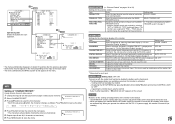
...• MAKE/TRIGGER terminal (RJ-45): The following items of this unit "SERIAL TYPE" setting "PARALLEL TYPE" setting - RS232C*1 - *1 For a monitor connected to . For other monitors, select "RS485." But certain external controls (starting/ terminating communication, turning on page 18) Set the following external control systems are available through the... RS-485 RS-232C The settings of "REMOTE SETTING" in SET-UP MENU according to "ON" (☞ page 15). • When the monitor is off (on page 15). PC, etc. RS-485 IN or RS-232C RS-485 RS-485 OUT IN • For the details, ...
...• MAKE/TRIGGER terminal (RJ-45): The following items of this unit "SERIAL TYPE" setting "PARALLEL TYPE" setting - RS232C*1 - *1 For a monitor connected to . For other monitors, select "RS485." But certain external controls (starting/ terminating communication, turning on page 18) Set the following external control systems are available through the... RS-485 RS-232C The settings of "REMOTE SETTING" in SET-UP MENU according to "ON" (☞ page 15). • When the monitor is off (on page 15). PC, etc. RS-485 IN or RS-232C RS-485 RS-485 OUT IN • For the details, ...

Instruction Manual
Page 17
... pin terminal for which functions in 1:1 mode. "PIN5") for about 1 second and opening it. 17 Controls whether displaying/hiding the wave form monitor (This function cannot be opened.) • When selecting the "TRIGGER" system, you want to be controlled with the TRIGGER system, the screen ...TALLY SEL Selects the color of the audio channel display is pressed (☞ "On the Status Display" on page 15 WAVE FORM Wave form monitor display COLOR OFF Color off - - - This is not displayed ("NO EFFECT" appears). While controlling with the TRIGGER system, the pattern of...
... pin terminal for which functions in 1:1 mode. "PIN5") for about 1 second and opening it. 17 Controls whether displaying/hiding the wave form monitor (This function cannot be opened.) • When selecting the "TRIGGER" system, you want to be controlled with the TRIGGER system, the screen ...TALLY SEL Selects the color of the audio channel display is pressed (☞ "On the Status Display" on page 15 WAVE FORM Wave form monitor display COLOR OFF Color off - - - This is not displayed ("NO EFFECT" appears). While controlling with the TRIGGER system, the pattern of...

Instruction Manual
Page 18
... terminal Cable Terminal specification Communication specifications RS-485 RS-232C A straight LAN cable A straight cable with a D-sub 9-pin connector (male for the monitor, female for the personal computer etc.) ☞ See below Baud Rate: 4800 bps Data Bits: 8 bits Parity: No parity Stop Bits: 1...the termination command from a personal computer etc. via the RS-485 or RS-232C terminal. • Consult your dealer for controlling all monitors at once. *2 Enter the appropriate data to "xx." *3 Displays the information shown when the INPUT SELECT button currently lit is pressed (&#...
... terminal Cable Terminal specification Communication specifications RS-485 RS-232C A straight LAN cable A straight cable with a D-sub 9-pin connector (male for the monitor, female for the personal computer etc.) ☞ See below Baud Rate: 4800 bps Data Bits: 8 bits Parity: No parity Stop Bits: 1...the termination command from a personal computer etc. via the RS-485 or RS-232C terminal. • Consult your dealer for controlling all monitors at once. *2 Enter the appropriate data to "xx." *3 Displays the information shown when the INPUT SELECT button currently lit is pressed (&#...
Instruction Manual
Page 19
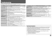
... the adjustment knobs on the menu. however, be aware that it remains for the current input or the current input signal are described here. The monitor emits a mechanical noise. 19 Page 6 8 8 8 6 8 - 9 6 6 8 - 7, 9 6 8 - 6, 14 6 14 14 Symptom The picture becomes blurred. Probable cause and ...the picture cannot be missing or constantly lit. • The following are not malfunctions. • When a still image is acceptable on the monitor. • Adjust the volume level. • Deactivate the muting function. • Connect the signal cable firmly. • Turn on the...
... the adjustment knobs on the menu. however, be aware that it remains for the current input or the current input signal are described here. The monitor emits a mechanical noise. 19 Page 6 8 8 8 6 8 - 9 6 6 8 - 7, 9 6 8 - 6, 14 6 14 14 Symptom The picture becomes blurred. Probable cause and ...the picture cannot be missing or constantly lit. • The following are not malfunctions. • When a still image is acceptable on the monitor. • Adjust the volume level. • Deactivate the muting function. • Connect the signal cable firmly. • Turn on the...
Instruction Manual
Page 20
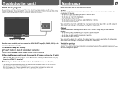
... easier. Whenever a problem occurs, one or some of the screen such as normal. If this product from the wall outlet before turning on the monitor soon after turning it off the screen with a soft cloth. If the screen gets heavily stained, wipe it with a soft cloth soaked in water.... Screen To avoid irreparable change in contact for a long time. • Do not wipe the cabinet forcefully. When this happens, turn on the monitor again. If the INPUT SELECT lamps do not flash, you can use a cloth and wipe it to resolve the problem. If the cabinet gets heavily...
... easier. Whenever a problem occurs, one or some of the screen such as normal. If this product from the wall outlet before turning on the monitor soon after turning it off the screen with a soft cloth. If the screen gets heavily stained, wipe it with a soft cloth soaked in water.... Screen To avoid irreparable change in contact for a long time. • Do not wipe the cabinet forcefully. When this happens, turn on the monitor again. If the INPUT SELECT lamps do not flash, you can use a cloth and wipe it to resolve the problem. If the cabinet gets heavily...
Instruction Manual
Page 21
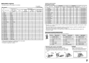
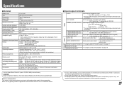
... Compliant video signal format Format Audio output Operating conditions Power requirements Rated current External dimensions (excluding protruding parts) Weight Accessories DT-V17L3D Multi format LCD monitor Type 17 wide format 16:10 17˝ wide, active matrix TFT Width: 367.2 mm (14 7/16˝)... HDCP): DVI-D connector x 1 (compatible with EMBEDDED AUDIO signals): E. Never use any packing material supplied from sources other than JVC or JVC-authorized dealers. • For easy understanding, pictures and illustrations are shown by being emphasized, omitted or composed, and may be slightly...
... Compliant video signal format Format Audio output Operating conditions Power requirements Rated current External dimensions (excluding protruding parts) Weight Accessories DT-V17L3D Multi format LCD monitor Type 17 wide format 16:10 17˝ wide, active matrix TFT Width: 367.2 mm (14 7/16˝)... HDCP): DVI-D connector x 1 (compatible with EMBEDDED AUDIO signals): E. Never use any packing material supplied from sources other than JVC or JVC-authorized dealers. • For easy understanding, pictures and illustrations are shown by being emphasized, omitted or composed, and may be slightly...

Instruction Manual
Page 24
DT-V17L3D MULTI FORMAT LCD MONITOR © 2008 Victor Company of Japan, Limited 0908TKH-MW-MT
DT-V17L3D MULTI FORMAT LCD MONITOR © 2008 Victor Company of Japan, Limited 0908TKH-MW-MT

