Instructions
Page 2
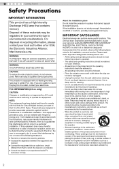
... BE EARTHED. If you are designed to insert the plug into the outlet, contact your community due to correct the interference by JVC could fall , causing serious injury to a child or adult, and serious damage to radio communications. These limits are unable to provide... reasonable protection against harmful interference in a residential installation. About the installation place Do not install the projector in the cabinet are provided for cleaning. - In order not to defeat the safeguards incorporated into an outlet on an unstable cart,...
... BE EARTHED. If you are designed to insert the plug into the outlet, contact your community due to correct the interference by JVC could fall , causing serious injury to a child or adult, and serious damage to radio communications. These limits are unable to provide... reasonable protection against harmful interference in a residential installation. About the installation place Do not install the projector in the cabinet are provided for cleaning. - In order not to defeat the safeguards incorporated into an outlet on an unstable cart,...
Instructions
Page 3
...impaired. - Never push objects of power source indicated on the product. - Never spill liquid of any kind into the inside of the projector could lead to normal operation. c) If the product has been exposed to injuries. The product should be routed so that they are not...extensive work by the manufacturer or with a three-wire plug. Pay particular attention to install the unit. Do not attempt to service this projector is damaged. Unplug this product, ask the service technician to perform safety checks to qualified service personnel. - When replacement parts are required...
...impaired. - Never push objects of power source indicated on the product. - Never spill liquid of any kind into the inside of the projector could lead to normal operation. c) If the product has been exposed to injuries. The product should be routed so that they are not...extensive work by the manufacturer or with a three-wire plug. Pay particular attention to install the unit. Do not attempt to service this projector is damaged. Unplug this product, ask the service technician to perform safety checks to qualified service personnel. - When replacement parts are required...

Instructions
Page 4
If nonetheless the mains plug is cut off , dispose of the plug immediately, to avoid a possible shock hazard by inadvertent connection to the main supply. and-yellow. The wire which is colored blue must be connected to be fitted, then follow the instruction given below. 1 Getting Started Safety Precautions (Continued) POWER CONNECTION WARNING: Do not cut off the main plug from this product are colored in your dealer. If a new main plug has to the terminal which is marked with the colored making identifying the terminals in accordance with the following cord: Green-...
If nonetheless the mains plug is cut off , dispose of the plug immediately, to avoid a possible shock hazard by inadvertent connection to the main supply. and-yellow. The wire which is colored blue must be connected to be fitted, then follow the instruction given below. 1 Getting Started Safety Precautions (Continued) POWER CONNECTION WARNING: Do not cut off the main plug from this product are colored in your dealer. If a new main plug has to the terminal which is marked with the colored making identifying the terminals in accordance with the following cord: Green-...

Instructions
Page 5
ENGLISH 5 Getting Started Preparation Basic Operation Settings Troubleshooting Others
ENGLISH 5 Getting Started Preparation Basic Operation Settings Troubleshooting Others

Instructions
Page 6
Main Features Supports Multiple Digital Devices zComes with a dual HDMI terminal that allows digital transmission of high definition signals. (pP14) 6
Main Features Supports Multiple Digital Devices zComes with a dual HDMI terminal that allows digital transmission of high definition signals. (pP14) 6
Instructions
Page 7
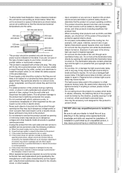
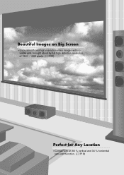
Getting Started Preparation Basic Operation Settings Beautiful Images on Big Screen zEnjoy smooth and high resolution video images with no visible grid, brought about by full high definition resolution of 1920 c 1080 pixels. (pP20) Perfect for Any Location zComes with an 80 % vertical and 34 % horizontal lens shift function. (pP18) 7 Troubleshooting Others
Getting Started Preparation Basic Operation Settings Beautiful Images on Big Screen zEnjoy smooth and high resolution video images with no visible grid, brought about by full high definition resolution of 1920 c 1080 pixels. (pP20) Perfect for Any Location zComes with an 80 % vertical and 34 % horizontal lens shift function. (pP18) 7 Troubleshooting Others
Instructions
Page 8
... via HDMI Cable 16 Connecting via HDMI-DVI Conversion Cable 16 Connecting via SCART-RCA Cable 17 Connecting via RGB Video Cable 17 Installing the Projector and Screen 18 Screen Size and Projection Distance 19 Troubleshooting Troubleshooting 36 What to Do When These Messages Are Displayed 38 About Warning Indicators 39...
... via HDMI Cable 16 Connecting via HDMI-DVI Conversion Cable 16 Connecting via SCART-RCA Cable 17 Connecting via RGB Video Cable 17 Installing the Projector and Screen 18 Screen Size and Projection Distance 19 Troubleshooting Troubleshooting 36 What to Do When These Messages Are Displayed 38 About Warning Indicators 39...
Instructions
Page 9
SHARP - ON OPERATE COMP HDMI 1 HDMI 2 VIDCEIONEMA S-VIDNEAOTURALANSPEDCYT NAMICD USER2 C USER1 COLO+R USER3 SHAR+P GAMMA SHAR-P COLO-RCONTRAST COTLBEOMRRPIGHT INFO HIDE MENU EXIT ENTER TEST LIGHT Remote Control AAA size Batteries (for details. z Replacement Lamp: BHL5009-S (Lamp Unit) z Replacement Filter: LC32058-002A (Inner Filter) Settings Troubleshooting Others 9 z Buttons on the menu are colored in this Manual C N D USER 1 USER 2 USER 3 COLOR + SHARP + GAMMA COLOR - This manual mainly describes the operating method using the remote control....
SHARP - ON OPERATE COMP HDMI 1 HDMI 2 VIDCEIONEMA S-VIDNEAOTURALANSPEDCYT NAMICD USER2 C USER1 COLO+R USER3 SHAR+P GAMMA SHAR-P COLO-RCONTRAST COTLBEOMRRPIGHT INFO HIDE MENU EXIT ENTER TEST LIGHT Remote Control AAA size Batteries (for details. z Replacement Lamp: BHL5009-S (Lamp Unit) z Replacement Filter: LC32058-002A (Inner Filter) Settings Troubleshooting Others 9 z Buttons on the menu are colored in this Manual C N D USER 1 USER 2 USER 3 COLOR + SHARP + GAMMA COLOR - This manual mainly describes the operating method using the remote control....
Instructions
Page 10
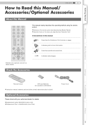
1 Getting Started Controls and Features To adjust the focus. Remove the buffer material before use . (pP50) „ Front Side/Left Side Remote Sensor (pP13) Air Inlets Lamp Cover (pP40) Lens Cap Exhaust Vent „Rear Side/Top Surface Remote Sensor (pP13) To connect the power cord (pP20) 10 z Do not throw away the buffer material, retain for future use . To adjust the size of the image. z Operate using the remote control. (pP20) CAUTION z Do not turn the lens with buffer material that cushions the lens. z This unit comes with your hands.
1 Getting Started Controls and Features To adjust the focus. Remove the buffer material before use . (pP50) „ Front Side/Left Side Remote Sensor (pP13) Air Inlets Lamp Cover (pP40) Lens Cap Exhaust Vent „Rear Side/Top Surface Remote Sensor (pP13) To connect the power cord (pP20) 10 z Do not throw away the buffer material, retain for future use . To adjust the size of the image. z Operate using the remote control. (pP20) CAUTION z Do not turn the lens with buffer material that cushions the lens. z This unit comes with your hands.
Instructions
Page 11
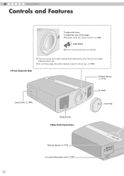
Basic Operation Settings Troubleshooting Others Air Inlets/Filter (pP43) To adjust the position of the image (pP19) 11 Getting Started Preparation ENGLISH Light on (Red): Standby mode Light on (Green): During projection Blinking (Green): Image is temporarily hidden (pP21) Blinking (Red): Cool Down mode (pP21) To switch input (pP20) To display the menu (pP24) WARNING LAMP STANDBY/ON STANDBY/ON INPUT HIDE MENU EXIT ENTER Light on (Red): Warning mode (pP39) Light on/Blinking (Orange): Lamp warning (pP39) To turn on/off the power To hide the image temporarily (pP21) To return to...
Basic Operation Settings Troubleshooting Others Air Inlets/Filter (pP43) To adjust the position of the image (pP19) 11 Getting Started Preparation ENGLISH Light on (Red): Standby mode Light on (Green): During projection Blinking (Green): Image is temporarily hidden (pP21) Blinking (Red): Cool Down mode (pP21) To switch input (pP20) To display the menu (pP24) WARNING LAMP STANDBY/ON STANDBY/ON INPUT HIDE MENU EXIT ENTER Light on (Red): Warning mode (pP39) Light on/Blinking (Orange): Lamp warning (pP39) To turn on/off the power To hide the image temporarily (pP21) To return to...
Instructions
Page 12
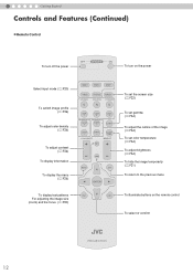
... the focus. (pP20) HDMI 1 HDMI 2 COMP. 1 Getting Started Controls and Features (Continued) „ Remote Control To turn on the remote control To select or confirm PROJECTOR 12
... the focus. (pP20) HDMI 1 HDMI 2 COMP. 1 Getting Started Controls and Features (Continued) „ Remote Control To turn on the remote control To select or confirm PROJECTOR 12
Instructions
Page 13
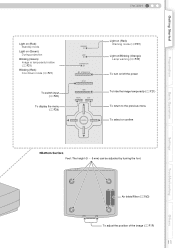
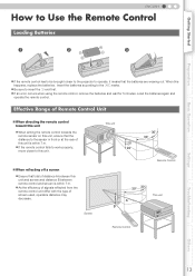
.... Getting Started Preparation Basic Operation ENGLISH How to Use the Remote Control Loading Batteries 1 2 3 z If the remote control has to be brought closer to the projector to operate, it means that total of distance A between this unit is within 7 m.
.... Getting Started Preparation Basic Operation ENGLISH How to Use the Remote Control Loading Batteries 1 2 3 z If the remote control has to be brought closer to the projector to operate, it means that total of distance A between this unit is within 7 m.

Instructions
Page 14
z For audio output, connect the device to the device used. Use an HDMI compliant cable (sold separately) with the HDMI logo. z The images may not be possible to connect to this unit depending on the dimension of the connector cover of the device to be connected. DVD Recorder DVD Player To connect via HDMI terminal (pP16) To connect RS-232C terminal To connect via component video terminals (pP15) HDMI 2 HDMI 1 RS-232C COMPONENT S-VIDEO VIDEO Y CB/PB CR/PR SYNC G B R To connect via video terminal (pP15) To connect via S-video terminal (pP15) Notebook PC 14 VCR and ...
z For audio output, connect the device to the device used. Use an HDMI compliant cable (sold separately) with the HDMI logo. z The images may not be possible to connect to this unit depending on the dimension of the connector cover of the device to be connected. DVD Recorder DVD Player To connect via HDMI terminal (pP16) To connect RS-232C terminal To connect via component video terminals (pP15) HDMI 2 HDMI 1 RS-232C COMPONENT S-VIDEO VIDEO Y CB/PB CR/PR SYNC G B R To connect via video terminal (pP15) To connect via S-video terminal (pP15) Notebook PC 14 VCR and ...
Instructions
Page 15
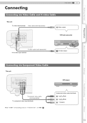
...Connecting Connecting via Video Cable and S-video Cable ENGLISH This unit To video input terminal Video cable (sold separately) Video output HD RS-232C OMPONENT S-VIDEO VIDEO Y CB/PB CR/PR SYNC G B R VCR and camcorder S-video cable (sold separately)... To S-video input terminal S-video output Preparation Basic Operation Settings Troubleshooting Connecting via Component Video Cable This unit HD RS-232C OMPONENT S-VIDEO VIDEO Y CB/PB CR/PR SYNC G B R Component video cable (sold separately) To component video input terminals ...
...Connecting Connecting via Video Cable and S-video Cable ENGLISH This unit To video input terminal Video cable (sold separately) Video output HD RS-232C OMPONENT S-VIDEO VIDEO Y CB/PB CR/PR SYNC G B R VCR and camcorder S-video cable (sold separately)... To S-video input terminal S-video output Preparation Basic Operation Settings Troubleshooting Connecting via Component Video Cable This unit HD RS-232C OMPONENT S-VIDEO VIDEO Y CB/PB CR/PR SYNC G B R Component video cable (sold separately) To component video input terminals ...

Instructions
Page 16
2 Preparation Connecting (Continued) Connecting via HDMI Cable This unit HDMI 2 HDMI 1 RS-232C COMPONENT S-VIDEO VIDEO Y CB/PB CR/PR SYNC G B R To HDMI 1 or HDMI 2 input terminal HDMI cable (sold separately) DVD recorder HDMI output terminal Connecting via HDMI-DVI Conversion Cable This unit MDMI 2 MDMI 1 RS-232C COMPONENT S-VIDEO VIDEO Y CB/PB CR/PR SYNC G B R Notebook PC To HDMI 1 or HDMI 2 input terminal HDMI-DVI conversion cable (sold separately) DVI output terminal 16
2 Preparation Connecting (Continued) Connecting via HDMI Cable This unit HDMI 2 HDMI 1 RS-232C COMPONENT S-VIDEO VIDEO Y CB/PB CR/PR SYNC G B R To HDMI 1 or HDMI 2 input terminal HDMI cable (sold separately) DVD recorder HDMI output terminal Connecting via HDMI-DVI Conversion Cable This unit MDMI 2 MDMI 1 RS-232C COMPONENT S-VIDEO VIDEO Y CB/PB CR/PR SYNC G B R Notebook PC To HDMI 1 or HDMI 2 input terminal HDMI-DVI conversion cable (sold separately) DVI output terminal 16
Instructions
Page 17
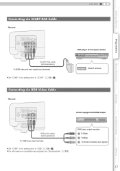
...) RGB video output terminals R (Red) B (Blue) G (Green) (Includes sync signal) Settings Troubleshooting Others 17 Q) Connecting via SCART-RCA Cable This unit HD RS-232C OMPONENT S-VIDEO VIDEO Y CB/PB CR/PR SYNC G B R SCART-RCA cable (sold separately) To RGB video input terminals z Set "COMP"..."RGB". (pP28 - Getting Started Preparation Basic Operation ENGLISH Connecting via RGB Video Cable This unit DVD player for European market SCART terminal HD RS-232C OMPONENT S-VIDEO VIDEO Y CB/PB CR/PR SYNC G B R Device equipped with RGB output RGB video cable (sold ...
...) RGB video output terminals R (Red) B (Blue) G (Green) (Includes sync signal) Settings Troubleshooting Others 17 Q) Connecting via SCART-RCA Cable This unit HD RS-232C OMPONENT S-VIDEO VIDEO Y CB/PB CR/PR SYNC G B R SCART-RCA cable (sold separately) To RGB video input terminals z Set "COMP"..."RGB". (pP28 - Getting Started Preparation Basic Operation ENGLISH Connecting via RGB Video Cable This unit DVD player for European market SCART terminal HD RS-232C OMPONENT S-VIDEO VIDEO Y CB/PB CR/PR SYNC G B R Device equipped with RGB output RGB video cable (sold ...
Instructions
Page 18
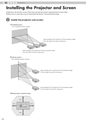
A Install the projector and screen „ Left/Right position *0 % up/down position (center) Approximately 34 % (maximum) of the projected image (Turn the dial to the right for maximum) ...; Up/Down position *0 % left/right position (center) Approximately 80 % (maximum) of the projected image (Turn the dial to the left for maximum) 2 Preparation Installing the Projector and Screen Install this unit and the screen perpendicular to the right for maximum) „ Shifting range of projected image 34% 80% MDMI 2 MDMI 1 RS...
A Install the projector and screen „ Left/Right position *0 % up/down position (center) Approximately 34 % (maximum) of the projected image (Turn the dial to the right for maximum) ...; Up/Down position *0 % left/right position (center) Approximately 80 % (maximum) of the projected image (Turn the dial to the left for maximum) 2 Preparation Installing the Projector and Screen Install this unit and the screen perpendicular to the right for maximum) „ Shifting range of projected image 34% 80% MDMI 2 MDMI 1 RS...

Instructions
Page 19
Approx. Approx. Approx. Approx. 3.63 m f 7.31 m 200" (Approx. 5.08 m) 130" (Approx. 3.30 m) Approx. Others 19 f 1.78 m 3.63 m 140" (Approx. 3.56 m) 70" (Approx. 1.78 m) Approx. f 4.24 m 8.54 m Approx. Approx. 4.86 m f 9.77 m Approx. Approx. Approx. Approx. 6.08 m f 12.23 m z The projection distances in the table are provided only as a reference during installation. J) Basic Operation Settings Troubleshooting Screen Size and Projection Distance Determine the distance from the lens to the screen to set "Pixel Adjust" in the setting menu ...
Approx. Approx. Approx. Approx. 3.63 m f 7.31 m 200" (Approx. 5.08 m) 130" (Approx. 3.30 m) Approx. Others 19 f 1.78 m 3.63 m 140" (Approx. 3.56 m) 70" (Approx. 1.78 m) Approx. f 4.24 m 8.54 m Approx. Approx. 4.86 m f 9.77 m Approx. Approx. Approx. Approx. 6.08 m f 12.23 m z The projection distances in the table are provided only as a reference during installation. J) Basic Operation Settings Troubleshooting Screen Size and Projection Distance Determine the distance from the lens to the screen to set "Pixel Adjust" in the setting menu ...
Instructions
Page 20
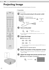
... D USER 1 USER 2 USER 3 COLOR + SHARP + GAMMA COLOR - SHARP - CONTRAST COLOR TEMP BRIGHT INFO HIDE MENU EXIT ENTER TEST LIGHT PROJECTOR WARNING LAMP STANDBY/ON A Connect to this unit B Connect to turn on adjusting the position. (pP18) Adjust the image size (zoom) and the focus...INPUT] button on the unit. (pP11) b Play back the selected device D Adjust the position of the projection screen E z See "Installing the Projector and Screen" for procedures on the power. (pP11) Project the image a Select input mode HDMI 1 HDMI 2 COMP. ON Preparation z Remove ...
... D USER 1 USER 2 USER 3 COLOR + SHARP + GAMMA COLOR - SHARP - CONTRAST COLOR TEMP BRIGHT INFO HIDE MENU EXIT ENTER TEST LIGHT PROJECTOR WARNING LAMP STANDBY/ON A Connect to this unit B Connect to turn on adjusting the position. (pP18) Adjust the image size (zoom) and the focus...INPUT] button on the unit. (pP11) b Play back the selected device D Adjust the position of the projection screen E z See "Installing the Projector and Screen" for procedures on the power. (pP11) Project the image a Select input mode HDMI 1 HDMI 2 COMP. ON Preparation z Remove ...
Instructions
Page 21
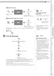
z The power cannot be turned off within approximately 90 seconds after it has been turned on. z During Cool Down mode, the [STANDBY/ON] indicator blinks in red. This may shorten the lamp life and cause a malfunction. Settings Troubleshooting Others 21 MEMO About Cool Down mode z The Cool Down mode is a function to cool down the lamp for a prolonged time. This function prevents the internal parts of the unit from deformation or damage due to prevent the lens from dirt. It also prevents lamp blowout and premature shortening of the lamp. z Do not pull out the power plug ...
z The power cannot be turned off within approximately 90 seconds after it has been turned on. z During Cool Down mode, the [STANDBY/ON] indicator blinks in red. This may shorten the lamp life and cause a malfunction. Settings Troubleshooting Others 21 MEMO About Cool Down mode z The Cool Down mode is a function to cool down the lamp for a prolonged time. This function prevents the internal parts of the unit from deformation or damage due to prevent the lens from dirt. It also prevents lamp blowout and premature shortening of the lamp. z Do not pull out the power plug ...
