

45 pg user manual for BR-DV600U/E VTR (1130KB)
Page 4
... cassette recorder/player incorporates precision components. After cleaning the heads, check that will help you determine a maintenance schedule that recording and playback function properly before using the unit for reference only. ogy 5 DV in/...recorder/player. The information below will ensure optimum performance over a long period, your local JVC dealer for maintenance Depending on the operation time, clean, inspect or replace the following mechanism components. Hour meter indication The hour meter can be unlawful to how the unit is recorded exclusively for professional...
... cassette recorder/player incorporates precision components. After cleaning the heads, check that will help you determine a maintenance schedule that recording and playback function properly before using the unit for reference only. ogy 5 DV in/...recorder/player. The information below will ensure optimum performance over a long period, your local JVC dealer for maintenance Depending on the operation time, clean, inspect or replace the following mechanism components. Hour meter indication The hour meter can be unlawful to how the unit is recorded exclusively for professional...
45 pg user manual for BR-DV600U/E VTR (1130KB)
Page 9
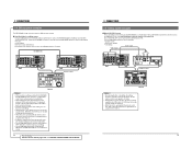
...uses the BR-DV600U as a feeder/player with an RS-422A serial remote controller such as the RM-G800, digital cut editing system Using an editing remote controller with JVC bus ... • Variable search • Slow-motion editing • CTL editing Audio signal Video signal DV IN/OUT Y/C VIDEO LINE IN COMPONENT R-Y B-Y Y AUDIO CH 1/3 CH 2/4 IN IN OUT...MANUAL TAKE SHIFT PREVIEW REVIEW ENTRY MENU CANCEL GOTO PLAYER P STOP STILL RECORDER R X-1 X1 AUTO EDIT ALL STOP IN ENTRY OUT REV FWD RM-G800 Notes: • When used in an editing system with the RM-G800, the BR...
...uses the BR-DV600U as a feeder/player with an RS-422A serial remote controller such as the RM-G800, digital cut editing system Using an editing remote controller with JVC bus ... • Variable search • Slow-motion editing • CTL editing Audio signal Video signal DV IN/OUT Y/C VIDEO LINE IN COMPONENT R-Y B-Y Y AUDIO CH 1/3 CH 2/4 IN IN OUT...MANUAL TAKE SHIFT PREVIEW REVIEW ENTRY MENU CANCEL GOTO PLAYER P STOP STILL RECORDER R X-1 X1 AUTO EDIT ALL STOP IN ENTRY OUT REV FWD RM-G800 Notes: • When used in an editing system with the RM-G800, the BR...
45 pg user manual for BR-DV600U/E VTR (1130KB)
Page 10
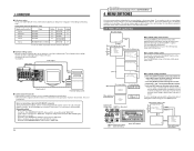
... display, the only difference being used ) Signal connection method Analog IEEE 1394 Analog Analog Player BR-DV600 BR-DV600 BR-DV600 BR-DV600 Analog BR-S800/BR-S500 (+ SA-N50)* Setting 0 F 0 F 0 F 0 F --- Menu switch...screen display or the counter display. To access another device via the DV connector • When the DV connector is used as a recorder Set the No. 108 menu switch to "IEEE 1394". • ...editing system 5 Control via the [DV INPUT] connector Set the No. 050 menu switch to "IEEE 1394". 16 For servicing → See the service manual page 1-10 "1.6 SERVICE MENU". ...
... display, the only difference being used ) Signal connection method Analog IEEE 1394 Analog Analog Player BR-DV600 BR-DV600 BR-DV600 BR-DV600 Analog BR-S800/BR-S500 (+ SA-N50)* Setting 0 F 0 F 0 F 0 F --- Menu switch...screen display or the counter display. To access another device via the DV connector • When the DV connector is used as a recorder Set the No. 108 menu switch to "IEEE 1394". • ...editing system 5 Control via the [DV INPUT] connector Set the No. 050 menu switch to "IEEE 1394". 16 For servicing → See the service manual page 1-10 "1.6 SERVICE MENU". ...
45 pg user manual for BR-DV600U/E VTR (1130KB)
Page 11
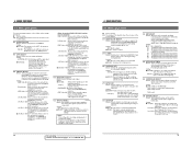
... connected to the [SYNC IN] connector. JVC BUS + RS422A (12): Allows control of this unit with the controller connected to the [REMOTE 2] and [DV IN/ OUT] connectors. RS232C (02): ... is repeated without applying a setup suitable to video signals. 18 For servicing See the service manual page 1-19 "1.11 SET UP SW". ← 4 MENU SWITCHES 4-2 Menu switch details ... kHz sampling frequency. qON (01): Activates the V. Setting: 32K (00): Records signals at the tag recording during recording or playback. Audio dubbing is rewound to the [AUDIO OUT] and [AUDIO ...
... connected to the [SYNC IN] connector. JVC BUS + RS422A (12): Allows control of this unit with the controller connected to the [REMOTE 2] and [DV IN/ OUT] connectors. RS232C (02): ... is repeated without applying a setup suitable to video signals. 18 For servicing See the service manual page 1-19 "1.11 SET UP SW". ← 4 MENU SWITCHES 4-2 Menu switch details ... kHz sampling frequency. qON (01): Activates the V. Setting: 32K (00): Records signals at the tag recording during recording or playback. Audio dubbing is rewound to the [AUDIO OUT] and [AUDIO ...
45 pg user manual for BR-DV600U/E VTR (1130KB)
Page 22
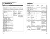
.... The tape ends. Turn the power on tapes recorded in the LP mode. If the problem persists, consult your nearest JVC dealer. Copy-guarded signals are possible. No operations are... a different tape. Operation stops. Set the safety slide to the [DV IN/ OUT] connector. Audio dubbing was recorded with the 48 kHz sampling rate. SSF INHIBIT SSFiNh FAN MOTOR FAILURE...fan motor stops (with a dedicated head cleaning tape. For servicing → See the service manual page 1-16 "1.7 WARNIGN CODES". 12 TROUBLESHOOTING 12-1 Warning indicators If the unit malfunctions during ...
.... The tape ends. Turn the power on tapes recorded in the LP mode. If the problem persists, consult your nearest JVC dealer. Copy-guarded signals are possible. No operations are... a different tape. Operation stops. Set the safety slide to the [DV IN/ OUT] connector. Audio dubbing was recorded with the 48 kHz sampling rate. SSF INHIBIT SSFiNh FAN MOTOR FAILURE...fan motor stops (with a dedicated head cleaning tape. For servicing → See the service manual page 1-16 "1.7 WARNIGN CODES". 12 TROUBLESHOOTING 12-1 Warning indicators If the unit malfunctions during ...

