
User Manual
Page 1
M-719200 Revision C1 12/2014 Copyright © 2014 JET This .pdf document is bookmarked Operating Instructions and Parts Manual 12x21-inch EVS Woodworking Lathe Model JWL-1221VS JET 427 New Sanford Road LaVergne, Tennessee 37086 Ph.: 800-274-6848 www.jettools.com Part No.
M-719200 Revision C1 12/2014 Copyright © 2014 JET This .pdf document is bookmarked Operating Instructions and Parts Manual 12x21-inch EVS Woodworking Lathe Model JWL-1221VS JET 427 New Sanford Road LaVergne, Tennessee 37086 Ph.: 800-274-6848 www.jettools.com Part No.
User Manual
Page 2
... accidents, normal wear-and-tear, improper repair, alterations or lack of its successors in JET printed materials and on This Warranty JET LIMITS ALL IMPLIED WARRANTIES TO THE PERIOD OF THE LIMITED WARRANTY FOR EACH PRODUCT. Product Listing with any of maintenance. Motors; Metalworking Machinery; Electric Hoists, Electric Hoist Accessories; VOLT Series Electric Hoists; Shop Tools; Warehouse & Dock products; Hand Tools NOTE: JET is constantly adding new products.
... accidents, normal wear-and-tear, improper repair, alterations or lack of its successors in JET printed materials and on This Warranty JET LIMITS ALL IMPLIED WARRANTIES TO THE PERIOD OF THE LIMITED WARRANTY FOR EACH PRODUCT. Product Listing with any of maintenance. Motors; Metalworking Machinery; Electric Hoists, Electric Hoist Accessories; VOLT Series Electric Hoists; Shop Tools; Warehouse & Dock products; Hand Tools NOTE: JET is constantly adding new products.
User Manual
Page 3
... face plate ...9 7.5 Installing/removing spur center ...10 7.6 Installing/removing live center ...10 8.0 Electrical connections ...11 8.1 Grounding instructions ...11 8.2 Extension cords...11 9.0 Adjustments ...12 9.1 Tool rest ...12 9.2 Tailstock ...12 9.3 Speed Change ...12 9.4 Index pin...13 10.0 Operating controls ...13 11.0 Operation ...14 11.1 Inspection ...14 11.2 Turning Tools ...14 11.3 Spindle Turning ...15 11.4 Face Plate and Bowl Turning ...17 11.5 Bowl Turning Techniques...18 12.0 Maintenance...19 12.1 General maintenance ...19 12.2 Motor Brushes ...20 12.3 Belt replacement...
... face plate ...9 7.5 Installing/removing spur center ...10 7.6 Installing/removing live center ...10 8.0 Electrical connections ...11 8.1 Grounding instructions ...11 8.2 Extension cords...11 9.0 Adjustments ...12 9.1 Tool rest ...12 9.2 Tailstock ...12 9.3 Speed Change ...12 9.4 Index pin...13 10.0 Operating controls ...13 11.0 Operation ...14 11.1 Inspection ...14 11.2 Turning Tools ...14 11.3 Spindle Turning ...15 11.4 Face Plate and Bowl Turning ...17 11.5 Bowl Turning Techniques...18 12.0 Maintenance...19 12.1 General maintenance ...19 12.2 Motor Brushes ...20 12.3 Belt replacement...
User Manual
Page 4
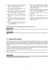
... not safety glasses. 11. Keep the floor around , carrying on this type of drugs, alcohol or any injury that can result in a well-ventilated area and work area and non-glare, overhead lighting. 7. Use recommended accessories; Do not operate this lathe for which it on. 14. Check damaged parts. Remove adjusting keys and wrenches. Some dust created by removing starter keys. 20. Do not turn materials...
... not safety glasses. 11. Keep the floor around , carrying on this type of drugs, alcohol or any injury that can result in a well-ventilated area and work area and non-glare, overhead lighting. 7. Use recommended accessories; Do not operate this lathe for which it on. 14. Check damaged parts. Remove adjusting keys and wrenches. Some dust created by removing starter keys. 20. Do not turn materials...
User Manual
Page 5
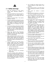
... even 4.0 About this manual This manual is not intended to lathe operational methods, use of accessories, choice of the type necessary for a JET Model JWL-1221VS Lathe. Do not stand on installation, safety precautions, general operating procedures, maintenance instructions and parts breakdown. Never apply coolants or water to remove chips or debris - If gluing up to a complete stop a rotating workpiece with the instructions as set forth in this manual: This means that...
... even 4.0 About this manual This manual is not intended to lathe operational methods, use of accessories, choice of the type necessary for a JET Model JWL-1221VS Lathe. Do not stand on installation, safety precautions, general operating procedures, maintenance instructions and parts breakdown. Never apply coolants or water to remove chips or debris - If gluing up to a complete stop a rotating workpiece with the instructions as set forth in this manual: This means that...
User Manual
Page 6
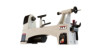
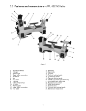
.... Tool rest base locking handle 26. JWL-1221VS lathe 1. Tailstock 9. Tailstock handwheel 10. Warning label 12. Lower pulley access door 13. Faceplate 15. Tool rest 17. Bed 7. DC motor 11. Speed chart 4. Tailstock locking handle 20. Upper pulley access door 5. Spur center 16. Tool rest locking handle 18. Headstock 6. Belt tension release lever 6 Index pin 3. Spindle handwheel 2. Variable speed dial (potentiometer) 21. 5.0 Features and nomenclature - On/off switch with safety key 22. Tool rest base...
.... Tool rest base locking handle 26. JWL-1221VS lathe 1. Tailstock 9. Tailstock handwheel 10. Warning label 12. Lower pulley access door 13. Faceplate 15. Tool rest 17. Bed 7. DC motor 11. Speed chart 4. Tailstock locking handle 20. Upper pulley access door 5. Spur center 16. Tool rest locking handle 18. Headstock 6. Belt tension release lever 6 Index pin 3. Spindle handwheel 2. Variable speed dial (potentiometer) 21. 5.0 Features and nomenclature - On/off switch with safety key 22. Tool rest base...
User Manual
Page 7
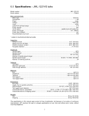
JWL-1221VS lathe Model number ...JWL-1221VS Stock number ...719200 Motor and electricals: Motor type ...120V DC Horsepower...1 HP Phase ...single Voltage ...115V only Cycle ...60Hz Listed FLA (full load amps) ...6 A Power transfer...belt On/off switch ...paddle style with safety key Power cord length ...6 ft. (183cm) Power plug installed ...yes Recommended circuit size1...10A 1 subject to change specifications at time of publication, but because of our policy of shipping carton 35.82"L x 14.56"W x 21...
JWL-1221VS lathe Model number ...JWL-1221VS Stock number ...719200 Motor and electricals: Motor type ...120V DC Horsepower...1 HP Phase ...single Voltage ...115V only Cycle ...60Hz Listed FLA (full load amps) ...6 A Power transfer...belt On/off switch ...paddle style with safety key Power cord length ...6 ft. (183cm) Power plug installed ...yes Recommended circuit size1...10A 1 subject to change specifications at time of publication, but because of our policy of shipping carton 35.82"L x 14.56"W x 21...
User Manual
Page 9
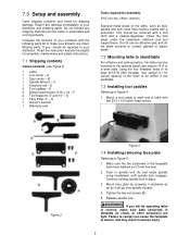
... holding spindle lock in the faceplate have been factory coated with a soft cloth and a cleaner-degreaser. Tighten the two set screws (B). 5. Read the instruction manual thoroughly for assembly: 3/16" hex key ("Allen" wrench) Exposed metal areas of the lathe, such as it will be removed with a protectant. H 1 Owner's manual 1 Warranty card Tools required for assembly, maintenance and safety instructions. 7.1 Shipping contents Carton contents (see section 14.0) or a work table, using handwheel, until...
... holding spindle lock in the faceplate have been factory coated with a soft cloth and a cleaner-degreaser. Tighten the two set screws (B). 5. Read the instruction manual thoroughly for assembly: 3/16" hex key ("Allen" wrench) Exposed metal areas of the lathe, such as it will be removed with a protectant. H 1 Owner's manual 1 Warranty card Tools required for assembly, maintenance and safety instructions. 7.1 Shipping contents Carton contents (see section 14.0) or a work table, using handwheel, until...

User Manual
Page 10
... spur center to prevent it from the sharp edges). Push live center: 3. Place wrench (C) over flats, and turn to unscrew faceplate. 7.5 Installing/removing spur center Referring to tap out spur center. 10 Engage spindle lock (A). 8. Use knockout rod through spindle hole to Figure 6: 1. Drive spur center into spindle. Rotate handwheel counterclockwise to retract quill, until center releases from falling. (You may occur. 7.
... spur center to prevent it from the sharp edges). Push live center: 3. Place wrench (C) over flats, and turn to unscrew faceplate. 7.5 Installing/removing spur center Referring to tap out spur center. 10 Engage spindle lock (A). 8. Use knockout rod through spindle hole to Figure 6: 1. Drive spur center into spindle. Rotate handwheel counterclockwise to retract quill, until center releases from falling. (You may occur. 7.

User Manual
Page 11
... a properly grounded outlet box. 8.1 Grounding instructions 1. Improper connection of power and overheating. The conductor with all local codes and ordinances. If an extension cord becomes necessary, be sure to use on cord length and nameplate ampere rating. Table 1 shows correct size to position equipment within reach of cord in off position. 8.0 Electrical connections The JWL-1221VS JET lathe is in feet More Than...
... a properly grounded outlet box. 8.1 Grounding instructions 1. Improper connection of power and overheating. The conductor with all local codes and ordinances. If an extension cord becomes necessary, be sure to use on cord length and nameplate ampere rating. Table 1 shows correct size to position equipment within reach of cord in off position. 8.0 Electrical connections The JWL-1221VS JET lathe is in feet More Than...
User Manual
Page 12
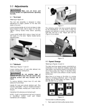
... end of bed. Open upper and lower pulley access doors. 12 9.0 Adjustments Make sure all levers and locking handles are tightened before operating the lathe. 9.1 Tool rest Referring to Figure 10: The tool rest assembly is designed to allow adjustment for height, position on tool rest base to slide base forward or back, and to angle it to the bed. This will result in position...
... end of bed. Open upper and lower pulley access doors. 12 9.0 Adjustments Make sure all levers and locking handles are tightened before operating the lathe. 9.1 Tool rest Referring to Figure 10: The tool rest assembly is designed to allow adjustment for height, position on tool rest base to slide base forward or back, and to angle it to the bed. This will result in position...
User Manual
Page 13
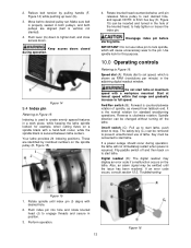
...: Speed dial (A): Rotate dial to set . Perform operation. 13 Figure 16 NOTE: A 3mm hex key (K, Figure 15) can be changed without turning off switch (C): Pull up lever (G). 3. Do not start lathe, push down to the pin. Fwd/Rev switch (B): Forward is shown as viewed from tailstock end. On/off the lathe. The safety key (C1) can be inserted and turned in a work piece, while keeping the lathe spindle locked...
...: Speed dial (A): Rotate dial to set . Perform operation. 13 Figure 16 NOTE: A 3mm hex key (K, Figure 15) can be changed without turning off switch (C): Pull up lever (G). 3. Do not start lathe, push down to the pin. Fwd/Rev switch (B): Forward is shown as viewed from tailstock end. On/off the lathe. The safety key (C1) can be inserted and turned in a work piece, while keeping the lathe spindle locked...
User Manual
Page 14
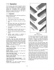
..., simple trial and error will keep the wheels true and eliminate glazing. Check belt; Bed ways; Parting Tool - 1/8", used to set diameters for shaping) and a 100-grit alum. however, a woodturner should be clean and free of dust and chips for scraping, making a cut , it should be sharpened. For best results, use a light touch. Lighting; Spindle Gouges - 1/4", 3/8", 1/2", used to sharpen tools freehand. The grinder should be ground past...
..., simple trial and error will keep the wheels true and eliminate glazing. Check belt; Bed ways; Parting Tool - 1/8", used to set diameters for shaping) and a 100-grit alum. however, a woodturner should be clean and free of dust and chips for scraping, making a cut , it should be sharpened. For best results, use a light touch. Lighting; Spindle Gouges - 1/4", 3/8", 1/2", used to sharpen tools freehand. The grinder should be ground past...
User Manual
Page 15
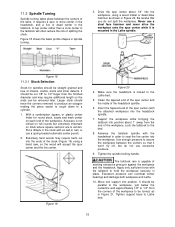
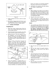
... kerfs cut into the workpiece, using a band saw, so the wood will often reduce the risk of the workpiece. Advance the tailstock spindle with an awl or nail, or use a steel face hammer and never drive the workpiece onto the spur center while it won't fly off, but extremely important on each end of splitting the stock. Tighten support base to...
... kerfs cut into the workpiece, using a band saw, so the wood will often reduce the risk of the workpiece. Advance the tailstock spindle with an awl or nail, or use a steel face hammer and never drive the workpiece onto the spur center while it won't fly off, but extremely important on each end of splitting the stock. Tighten support base to...
User Manual
Page 16
Rotate workpiece by hand to the desired depth. Begin with the workpiece. 3. Keep the skew handle perpendicular to the spindle and use only the center third of the cutting edge for a long smoothing cut (touching one of the points of cut. Place the parting tool on the surface to catch. Repeat for the size of the tool as much of the bevel of workpiece used. attempting...
Rotate workpiece by hand to the desired depth. Begin with the workpiece. 3. Keep the skew handle perpendicular to the spindle and use only the center third of the cutting edge for a long smoothing cut (touching one of the points of cut. Place the parting tool on the surface to catch. Repeat for the size of the tool as much of the bevel of workpiece used. attempting...

User Manual
Page 17
... the cut. Additional cuts may work fine if you select. Adjust lathe speed to the workpiece. Remove excess finish before restarting lathe. Select stock at the bottom and leave a clean "V" cut , raise the handle and push the tool in to a low speed, and begin with 320 or 400 grit sandpaper. Face plates are drilled for parting through each dimension on tool support and raise the handle until...
... the cut. Additional cuts may work fine if you select. Adjust lathe speed to the workpiece. Remove excess finish before restarting lathe. Select stock at the bottom and leave a clean "V" cut , raise the handle and push the tool in to a low speed, and begin with 320 or 400 grit sandpaper. Face plates are drilled for parting through each dimension on tool support and raise the handle until...
User Manual
Page 18
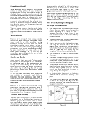
.... Tools for Bowl Turning be used for turning, chucks can handle. Slip the spur center into the headstock taper and bring it in others . Tighten the ram locking handle. 4. Rough out the outside of wood for extremely large pieces. A chuck is not a requirement, but is a problem associated with a mallet or dead blow hammer. 3. Checks and Cracks Green wood will vary from the pith. Cut...
.... Tools for Bowl Turning be used for turning, chucks can handle. Slip the spur center into the headstock taper and bring it in others . Tighten the ram locking handle. 4. Rough out the outside of wood for extremely large pieces. A chuck is not a requirement, but is a problem associated with a mallet or dead blow hammer. 3. Checks and Cracks Green wood will vary from the pith. Cut...

User Manual
Page 19
..., worn electrical cables, proper belt tension, belt wear, or any other . 10. Face off top of bowl. Turn lathe back on tool support at about 3" and use , and blow out chips and dust using only light pressure. This will be approximately 1/3 the overall diameter of finish. Rotate workpiece by making a light shearing cut almost all the way through yet. Remove the tool support and adjust lathe speed to...
..., worn electrical cables, proper belt tension, belt wear, or any other . 10. Face off top of bowl. Turn lathe back on tool support at about 3" and use , and blow out chips and dust using only light pressure. This will be approximately 1/3 the overall diameter of finish. Rotate workpiece by making a light shearing cut almost all the way through yet. Remove the tool support and adjust lathe speed to...

User Manual
Page 20
... the motor. Remove three button head screws to internal motor elements. 1. Release belt tension (see Figure 14), and open pulley access doors. 3. Engage spindle lock, and loosen both set screws (A) in spindle sensor collar (C). Note: The right side bearing will slide out with the spindle. Disconnect lathe from power. 2. Repeat inspection for brush on opposite side of wood, to lose these parts. Figure 28 12.3 Belt replacement Referring to remove.) 5. If brushes need replacing, replace...
... the motor. Remove three button head screws to internal motor elements. 1. Release belt tension (see Figure 14), and open pulley access doors. 3. Engage spindle lock, and loosen both set screws (A) in spindle sensor collar (C). Note: The right side bearing will slide out with the spindle. Disconnect lathe from power. 2. Repeat inspection for brush on opposite side of wood, to lose these parts. Figure 28 12.3 Belt replacement Referring to remove.) 5. If brushes need replacing, replace...
User Manual
Page 23
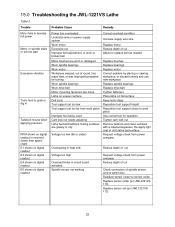
... oil to lathe bed surface. Worn motor Excessive cut Adjust or replace belt as needed Motor brushes are worn or damaged Worn spindle bearings Worn motor Workpiece warped, out of round, has major flaw, or was improperly prepared for operation Tighten cam lock nut Remove tailstock and clean surfaces with a cleaner/degreaser. Re-apply light coat of spindle sensor cord to switch box Readjust sensor closer to work piece Improper tool being used Cam lock nut needs adjusting...
... oil to lathe bed surface. Worn motor Excessive cut Adjust or replace belt as needed Motor brushes are worn or damaged Worn spindle bearings Worn motor Workpiece warped, out of round, has major flaw, or was improperly prepared for operation Tighten cam lock nut Remove tailstock and clean surfaces with a cleaner/degreaser. Re-apply light coat of spindle sensor cord to switch box Readjust sensor closer to work piece Improper tool being used Cam lock nut needs adjusting...


