
Product Specification
Page 9
... - Setup Utility - Floppy Order Screen Display 45 Figure 21. Setup Utility - Setup Utility - Setup Utility - Serial Port Configuration Screen Display 34 Figure 11. Security Screen Display 38 Figure 14. Setup Utility - Setup Utility -System Information Screen Display 42 Figure 17. Setup Utility - BEV Device Order Screen Display 46 Figure 23. BMC Power/Reset Signals 55 Figure 27. Location of Figures Figure 1. Advanced Screen Display 28 Figure 7. Memory Configuration Screen Display 31 Figure 9. Setup Utility - Intel® Server Board X38ML Layout...
... - Setup Utility - Floppy Order Screen Display 45 Figure 21. Setup Utility - Setup Utility - Setup Utility - Serial Port Configuration Screen Display 34 Figure 11. Security Screen Display 38 Figure 14. Setup Utility - Setup Utility -System Information Screen Display 42 Figure 17. Setup Utility - BEV Device Order Screen Display 46 Figure 23. BMC Power/Reset Signals 55 Figure 27. Location of Figures Figure 1. Advanced Screen Display 28 Figure 7. Memory Configuration Screen Display 31 Figure 9. Setup Utility - Intel® Server Board X38ML Layout...
Product Specification
Page 10
... 17. Setup Utility - Boot Options Screen Fields 43 Table 19. Hard Disk Order Fields 44 Table 20. Main Screen Fields 26 Table 7. Advanced Screen Display Fields 28 Table 8. Processor Configuration Screen Fields 29 Table 9. System Status LED Indicator States 62 Table 32. Serial B Header Pin-out 19 Table 4. BIOS Setup: Keyboard Command Bar 23 Table 6. Setup Utility - Serial Ports Configuration Screen Fields 34 Table 12. Setup Utility - Setup Utility - Setup Utility - ACPI Power States ...58 Table 29. List of Tables Intel® Server Board X38ML List of...
... 17. Setup Utility - Boot Options Screen Fields 43 Table 19. Hard Disk Order Fields 44 Table 20. Main Screen Fields 26 Table 7. Advanced Screen Display Fields 28 Table 8. Processor Configuration Screen Fields 29 Table 9. System Status LED Indicator States 62 Table 32. Serial B Header Pin-out 19 Table 4. BIOS Setup: Keyboard Command Bar 23 Table 6. Setup Utility - Serial Ports Configuration Screen Fields 34 Table 12. Setup Utility - Setup Utility - Setup Utility - ACPI Power States ...58 Table 29. List of Tables Intel® Server Board X38ML List of...
Product Specification
Page 11
.../1000) Connector Pin-out (J3A2 108 Table 58. Optional USB Connection Header Pin-out (J1B3 109 Table 63. 8-pin Fan Headers Pin-out (J5K1, J5K2, J5K3 110 Table 64. Standard Channel Assignments 73 Table 38. NIC2- Timestamp Clock Sync Format 97 Table 48. External DB-9 Serial A Port Pin-out (J5A1 108 Table 60. Keyboard Controller Style Interfaces 74 Table 39. Intel® Server Board X38ML List of Event Data Field Contents for PCI Errors 95...
.../1000) Connector Pin-out (J3A2 108 Table 58. Optional USB Connection Header Pin-out (J1B3 109 Table 63. 8-pin Fan Headers Pin-out (J5K1, J5K2, J5K3 110 Table 64. Standard Channel Assignments 73 Table 38. NIC2- Timestamp Clock Sync Format 97 Table 48. External DB-9 Serial A Port Pin-out (J5A1 108 Table 60. Keyboard Controller Style Interfaces 74 Table 39. Intel® Server Board X38ML List of Event Data Field Contents for PCI Errors 95...
Product Specification
Page 17
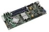
... of the server board: Revision 1.3 5 Intel order number E15331-006 Intel® Server Board X38ML Server Board Overview Ref # 3 4 5 6 7 8 9 10 11 12 13 14 15 16 Description NIC2 RJ-45 connector (J3A1) Integrated BMC Force Update Jumper Serial A DB-9 connector VGA connector Chassis intrusion header ServerEngines* Integrated BMC POST LED 2x5 USB header for USB 2 and 3 Intel® 82575EB LAN controller SMBus connector Intel® 82801IR ICH9R (J6B1) Password Clear jumper PCI Express* x16 riser slot SATA Port 2 Ref # 19 20 Description SATA Port 1 CMOS battery 21 1x3 Serial B header 22...
... of the server board: Revision 1.3 5 Intel order number E15331-006 Intel® Server Board X38ML Server Board Overview Ref # 3 4 5 6 7 8 9 10 11 12 13 14 15 16 Description NIC2 RJ-45 connector (J3A1) Integrated BMC Force Update Jumper Serial A DB-9 connector VGA connector Chassis intrusion header ServerEngines* Integrated BMC POST LED 2x5 USB header for USB 2 and 3 Intel® 82575EB LAN controller SMBus connector Intel® 82801IR ICH9R (J6B1) Password Clear jumper PCI Express* x16 riser slot SATA Port 2 Ref # 19 20 Description SATA Port 1 CMOS battery 21 1x3 Serial B header 22...
Product Specification
Page 20
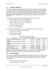
... the Intel® Server Board X38ML support Web site: http://support.intel.com/support/motherboards/server/X38ML/. 3.2 Intel® X38 Chipset The Intel® Server Board X38ML is designed around the Intel® X38 chipset. The processors supported with an LGA775 socket. Functional Architecture Intel® Server Board X38ML 3.1 Processor Subsystem The Intel® Server Board X38ML supports one Intel® Xeon® or workstation processor utilizing Flip-Chip Land Grid Array (LGA) package technology, with the Intel® Server Board X38ML are listed below: ƒ Dual-Core Intel...
... the Intel® Server Board X38ML support Web site: http://support.intel.com/support/motherboards/server/X38ML/. 3.2 Intel® X38 Chipset The Intel® Server Board X38ML is designed around the Intel® X38 chipset. The processors supported with an LGA775 socket. Functional Architecture Intel® Server Board X38ML 3.1 Processor Subsystem The Intel® Server Board X38ML supports one Intel® Xeon® or workstation processor utilizing Flip-Chip Land Grid Array (LGA) package technology, with the Intel® Server Board X38ML are listed below: ƒ Dual-Core Intel...
Product Specification
Page 21
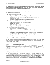
... reference clock shared with the PCI Express Base Specification, Revision 1.1. Intel® Server Board X38ML Functional Architecture The following sub-sections provide an overview of the primary functions and supported features of each direction. Each Root Port fully supports 2.5 Gb/s bandwidth in a UP System configuration - 200/266/333 MHz FSB clock frequency. One PCI Express* x16 port is connected to -chip connection between the Intel® X38 MCH and the Intel®...
... reference clock shared with the PCI Express Base Specification, Revision 1.1. Intel® Server Board X38ML Functional Architecture The following sub-sections provide an overview of the primary functions and supported features of each direction. Each Root Port fully supports 2.5 Gb/s bandwidth in a UP System configuration - 200/266/333 MHz FSB clock frequency. One PCI Express* x16 port is connected to -chip connection between the Intel® X38 MCH and the Intel®...
Product Specification
Page 22
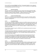
... the system timer, keyboard controller, serial ports, parallel ports, floppy disk, mouse, DMA channels, and mapped PCI-based interrupts. 3.2.2.6 Universal Serial Bus (USB) Controller The Intel® ICH9 contains two EHCI and six UHCI USB Controllers providing support for these three counters. USB 2.0 based debug port is used to 8-bit, count-by -word transfers. The SATA II Controller provides two modes of two 8237 DMA controllers, with seven independently programmable channels. The DMA controller incorporates the logic...
... the system timer, keyboard controller, serial ports, parallel ports, floppy disk, mouse, DMA channels, and mapped PCI-based interrupts. 3.2.2.6 Universal Serial Bus (USB) Controller The Intel® ICH9 contains two EHCI and six UHCI USB Controllers providing support for these three counters. USB 2.0 based debug port is used to 8-bit, count-by -word transfers. The SATA II Controller provides two modes of two 8237 DMA controllers, with seven independently programmable channels. The DMA controller incorporates the logic...
Product Specification
Page 24
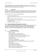
... if the processor fetches the first instruction after reset ƒ ECC Error reporting from the host controller ƒ Function Disable to prevent a disabled function from system lockups without the use of sockets. 3.2.2.12 Manageability The Intel® ICH9 integrates several functions to 3.6 volt serial interface FLASH memory, Intel part number D64145-001/D64145-002. Functional Architecture Intel® Server Board X38ML The SPI Flash Memory device is integrated onto the server board. This integrates...
... if the processor fetches the first instruction after reset ƒ ECC Error reporting from the host controller ƒ Function Disable to prevent a disabled function from system lockups without the use of sockets. 3.2.2.12 Manageability The Intel® ICH9 integrates several functions to 3.6 volt serial interface FLASH memory, Intel part number D64145-001/D64145-002. Functional Architecture Intel® Server Board X38ML The SPI Flash Memory device is integrated onto the server board. This integrates...
Product Specification
Page 38
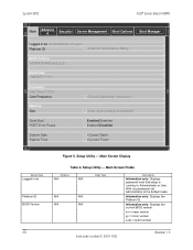
... version zzzz = build number Intel order number E15331-006 Revision 1.3 Displays the Platform ID. Displays password level that setup is the default mode. Information only. With no passwords set, Administrator is running in as Platform ID BIOS Version S3200X38.86B.xx.yy.zzzz Build Date Processor Intel® Xeon® CPU Core Frequency Memory Size Quiet Boot POST Error Pause Enabled/Disabled Enabled/Disabled System Date System Time Setup Item Logged in , Administrator or User. Displays the current BIOS version. Main Screen Display Table 6. Setup Utility...
... version zzzz = build number Intel order number E15331-006 Revision 1.3 Displays the Platform ID. Displays password level that setup is the default mode. Information only. With no passwords set, Administrator is running in as Platform ID BIOS Version S3200X38.86B.xx.yy.zzzz Build Date Processor Intel® Xeon® CPU Core Frequency Memory Size Quiet Boot POST Error Pause Enabled/Disabled Enabled/Disabled System Date System Time Setup Item Logged in , Administrator or User. Displays the current BIOS version. Main Screen Display Table 6. Setup Utility...
Product Specification
Page 40
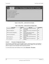
... core frequency, system bus frequency, and enable or disable several processor options. Setup Utility - N/A View/Configure USB information and settings. N/A View/Configure SATA Controller information and settings. Setup Utility - System BIOS Intel® Server Board X38ML Main Advance d Security Server Management Boot Options Boot Manager ► Processor Configuration ► Memory Configuration ► SATA Controller Configuration ► Serial Port Configuration ► USB Configuration ► PCI Configuration Figure 6. Advanced Screen Display...
... core frequency, system bus frequency, and enable or disable several processor options. Setup Utility - N/A View/Configure USB information and settings. N/A View/Configure SATA Controller information and settings. Setup Utility - System BIOS Intel® Server Board X38ML Main Advance d Security Server Management Boot Options Boot Manager ► Processor Configuration ► Memory Configuration ► SATA Controller Configuration ► Serial Port Configuration ► USB Configuration ► PCI Configuration Figure 6. Advanced Screen Display...
Product Specification
Page 44
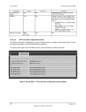
... Configuration Onboard SATA Controller Configure SATA as Enabled/Disabled IDE/AHCI/ RAID ► SATA Port 0 ► SATA Port 1 ► SATA Port 2 ► SATA Port 3 Not Installed/ Not Installed/ Not Installed/ Not Installed/ Figure 9. Displays speed the memory is faulty/malfunctioning. Each DIMM socket field reflects one of each DIMM socket present on the hard disk drives installed. ATA Controller Configuration Screen Display 32 Revision 1.3 Intel order number E15331-006 System BIOS Intel® Server Board X38ML Setup Item Current Memory Speed DIMM_# Options...
... Configuration Onboard SATA Controller Configure SATA as Enabled/Disabled IDE/AHCI/ RAID ► SATA Port 0 ► SATA Port 1 ► SATA Port 2 ► SATA Port 3 Not Installed/ Not Installed/ Not Installed/ Not Installed/ Figure 9. Displays speed the memory is faulty/malfunctioning. Each DIMM socket field reflects one of each DIMM socket present on the hard disk drives installed. ATA Controller Configuration Screen Display 32 Revision 1.3 Intel order number E15331-006 System BIOS Intel® Server Board X38ML Setup Item Current Memory Speed DIMM_# Options...
Product Specification
Page 45
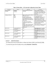
... (AHCI) option ROM will enumerate all AHCI devices connected to the AHCI Option ROM. When AHCI is selected: The identification and configuration is enabled. To access this feature. [RAID] - Only devices supported by the AHCI Option ROM are displayed in setup (SATA HDD and SATA CDROM) other devices are available in IDE, RAID, or AHCI Mode. Setup Utility - This field is unavailable when RAID Mode is left to the SATA ports. Intel® Server Board X38ML System BIOS Setup Item Onboard SATA Controller Configure SATA as SATA Port 0 SATA Port 1 SATA Port 2 SATA Port 3 Table...
... (AHCI) option ROM will enumerate all AHCI devices connected to the AHCI Option ROM. When AHCI is selected: The identification and configuration is enabled. To access this feature. [RAID] - Only devices supported by the AHCI Option ROM are displayed in setup (SATA HDD and SATA CDROM) other devices are available in IDE, RAID, or AHCI Mode. Setup Utility - This field is unavailable when RAID Mode is left to the SATA ports. Intel® Server Board X38ML System BIOS Setup Item Onboard SATA Controller Configure SATA as SATA Port 0 SATA Port 1 SATA Port 2 SATA Port 3 Table...
Product Specification
Page 49
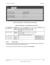
...Setup Utility - To access this screen from the Main screen, select the option Security. Intel® Server Board X38ML Advanced PCI Configuration Dual Monitor Video Onboard NIC ROM NIC 1 MAC Address NIC 2 MAC Address Enabled/Disabled Enabled/Disabled System BIOS Figure 12. PCI Configuration Screen Fields Options Enabled Disabled Enabled Disabled No entry allowed No entry allowed Help Text Both the onboard video controller and an add-in video adapter will be enabled for the onboard network controllers. PCI Configuration Screen Display Setup Item Dual Monitor Video Onboard NIC ROM...
...Setup Utility - To access this screen from the Main screen, select the option Security. Intel® Server Board X38ML Advanced PCI Configuration Dual Monitor Video Onboard NIC ROM NIC 1 MAC Address NIC 2 MAC Address Enabled/Disabled Enabled/Disabled System BIOS Figure 12. PCI Configuration Screen Fields Options Enabled Disabled Enabled Disabled No entry allowed No entry allowed Help Text Both the onboard video controller and an add-in video adapter will be enabled for the onboard network controllers. PCI Configuration Screen Display Setup Item Dual Monitor Video Onboard NIC ROM...
Product Specification
Page 50
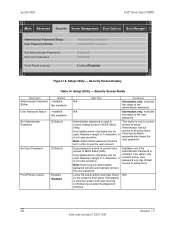
.... User password is selected, power and reset must be controlled via a system management interface. User password only has limited access to all setup items. Clearing the Admin password also clears the user password. Note: Removing the administrator password will also automatically remove the user password. System BIOS Intel® Server Board X38ML Main Advanced Security Server Management Boot Options Boot Manager Administrator Password Status User Password Status Set Administrator Password Set User Password Front Panel Lockout [123abcd] [123abcd] Enabled/Disabled Figure...
.... User password is selected, power and reset must be controlled via a system management interface. User password only has limited access to all setup items. Clearing the Admin password also clears the user password. Note: Removing the administrator password will also automatically remove the user password. System BIOS Intel® Server Board X38ML Main Advanced Security Server Management Boot Options Boot Manager Administrator Password Status User Password Status Set Administrator Password Set User Password Front Panel Lockout [123abcd] [123abcd] Enabled/Disabled Figure...
Product Specification
Page 56
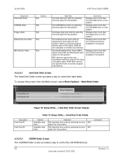
... control the CD-ROM devices. 44 Intel order number E15331-006 Revision 1.3 BEV devices are two examples of these devices is available in the system. 4.3.2.5.1 Hard Disk Order Screen The Hard Disk Order screen provides a way to control the hard disks. To access this position. System BIOS Intel® Server Board X38ML Setup Item Hard Disk Order Options N/A CDROM Order N/A Floppy Order N/A Network Device Order N/A BEV Device Order N/A Help Text Set hard disk boot order by selecting the boot option for this screen from the Main screen, select Boot Options > Hard Disk...
... control the CD-ROM devices. 44 Intel order number E15331-006 Revision 1.3 BEV devices are two examples of these devices is available in the system. 4.3.2.5.1 Hard Disk Order Screen The Hard Disk Order screen provides a way to control the hard disks. To access this position. System BIOS Intel® Server Board X38ML Setup Item Hard Disk Order Options N/A CDROM Order N/A Floppy Order N/A Network Device Order N/A BEV Device Order N/A Help Text Set hard disk boot order by selecting the boot option for this screen from the Main screen, select Boot Options > Hard Disk...
Product Specification
Page 63
... system loads and executes the flash update application, IFLASH32.EFI. The user powers off the system and moves the recovery jumper back to recovery operation. The OEM firmware volume hosts a firmware file system. The BIOS detects that uses the new capture file (*.CAP). The user inserts the recovery medium and powers on the file name. Intel® Server Board X38ML System BIOS 4.6 Recovery Mode You can include the OEM splash logo. Recovery from a SATA CD-ROM and USB mass storage device...
... system loads and executes the flash update application, IFLASH32.EFI. The user powers off the system and moves the recovery jumper back to recovery operation. The OEM firmware volume hosts a firmware file system. The BIOS detects that uses the new capture file (*.CAP). The user inserts the recovery medium and powers on the file name. Intel® Server Board X38ML System BIOS 4.6 Recovery Mode You can include the OEM splash logo. Recovery from a SATA CD-ROM and USB mass storage device...
Product Specification
Page 100
... BIOS Reference Specification, Version 2.5, to create a standardized interface for the onboard controllers. If only one password is set, the password is not case-sensitive. Platform Management Intel® Server Board X38ML Legacy Console Redirection: The BIOS enables Legacy operating system redirection on the SOL console. 5.23.4 Wired For Management (WFM) Wired for the installed network interface card must be entered before a user password can obtain the types, capabilities, operational status, installation date, and other information about the access...
... BIOS Reference Specification, Version 2.5, to create a standardized interface for the onboard controllers. If only one password is set, the password is not case-sensitive. Platform Management Intel® Server Board X38ML Legacy Console Redirection: The BIOS enables Legacy operating system redirection on the SOL console. 5.23.4 Wired For Management (WFM) Wired for the installed network interface card must be entered before a user password can obtain the types, capabilities, operational status, installation date, and other information about the access...
Product Specification
Page 103
... the server management firmware. Disabling NMI for PERR#. and multi-bit errors Sensors Errors detected during POST, logged as a group can be logged. These are defined. 6.2.1 Error Sources and Types One of the major requirements of server management is enabled in Section 6.2.3.3. 6.2.2.2 PCI Express* Errors The hardware is capable of PERR#, the PCI bus master has the option to retry the offending transaction, or to enable or disable reporting...
... the server management firmware. Disabling NMI for PERR#. and multi-bit errors Sensors Errors detected during POST, logged as a group can be logged. These are defined. 6.2.1 Error Sources and Types One of the major requirements of server management is enabled in Section 6.2.3.3. 6.2.2.2 PCI Express* Errors The hardware is capable of PERR#, the PCI bus master has the option to retry the offending transaction, or to enable or disable reporting...
Product Specification
Page 109
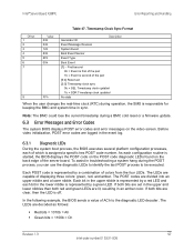
... cold reset or a firmware update. 6.3 Error Messages and Error Codes The system BIOS displays POST error codes and error messages on the video screen. Timestamp Clock Sync Format Offset 1 2 3 4 5 6 7 8 Value 03h 04h 12h 83h 6Fh 05h FFh Generator ID Description Event Message Revision System Event Boot Event Sensor Event Type Boot Event [7] - Before video initialization, POST error codes are clear, then the LED is represented by a red LED and each bit in sync. The LEDs are divided...
... cold reset or a firmware update. 6.3 Error Messages and Error Codes The system BIOS displays POST error codes and error messages on the video screen. Timestamp Clock Sync Format Offset 1 2 3 4 5 6 7 8 Value 03h 04h 12h 83h 6Fh 05h FFh Generator ID Description Event Message Revision System Event Boot Event Sensor Event Type Boot Event [7] - Before video initialization, POST error codes are clear, then the LED is represented by a red LED and each bit in sync. The LEDs are divided...
Product Specification
Page 115
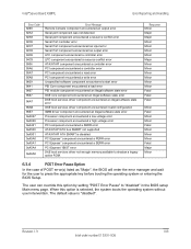
... Minor Fatal Minor Minor Minor Fatal Major Minor 6.3.4 POST Error Pause Option In the case of POST error(s) listed as "Major", the BIOS will enter the error manager and wait for the user to shadow a legacy option ROM. When this option by setting "POST Error Pause" to "disabled" in the BIOS setup Main menu page. Revision 1.3 103 Intel order number E15331-006 Intel® Server Board X38ML Error Reporting and Handling Error Code 9288 92A3 92A9 92C6 92C7 92C8 94C6 94C9...
... Minor Fatal Minor Minor Minor Fatal Major Minor 6.3.4 POST Error Pause Option In the case of POST error(s) listed as "Major", the BIOS will enter the error manager and wait for the user to shadow a legacy option ROM. When this option by setting "POST Error Pause" to "disabled" in the BIOS setup Main menu page. Revision 1.3 103 Intel order number E15331-006 Intel® Server Board X38ML Error Reporting and Handling Error Code 9288 92A3 92A9 92C6 92C7 92C8 94C6 94C9...


