Design Guide
Page 14
... • Intel® 820 Chipset: Intel® 82820 Memory Controller Hub (MCH) Datasheet (Order Number: 290630) • Intel® 82801AA (ICH) and Intel® 82801AB (ICH0) I /O subsystem of Intel chipsets. This removes many of the conflicts experienced when installing hardware and drivers into legacy ...interconnect, the hub interface, is the third generation desktop chipset designed for the Intel® 820 chipset platform. Support of the high performance provided by the powerful Pentium III processor. In addition, the Intel® 820 chipset architecture enables a new security...
... • Intel® 820 Chipset: Intel® 82820 Memory Controller Hub (MCH) Datasheet (Order Number: 290630) • Intel® 82801AA (ICH) and Intel® 82801AB (ICH0) I /O subsystem of Intel chipsets. This removes many of the conflicts experienced when installing hardware and drivers into legacy ...interconnect, the hub interface, is the third generation desktop chipset designed for the Intel® 820 chipset platform. Support of the high performance provided by the powerful Pentium III processor. In addition, the Intel® 820 chipset architecture enables a new security...

Design Guide
Page 77
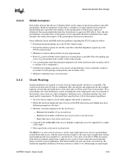
... the VR). CPU0 and CPU1 should have internal pull-ups. Connect to VCCCORE, use ganged clock. This checklist supports Intel® Pentium® II processors at the clock driver then route to simulate based on BSEL0 negates PWRGOOD 220 Ω pull up to 3.3V, connected to PWRGOOD logic ...CPU0. 1 K -100 KΩ pull up to Vcc2.5 If a legacy design pulls this up to GND. Some of direct connection to simulate based on -board VR or VRM. Connect to gate system from CPU0. Use separate PICCLK from powering on simulation results. Tie to any voltage. Single-ended termination is...
... the VR). CPU0 and CPU1 should have internal pull-ups. Connect to VCCCORE, use ganged clock. This checklist supports Intel® Pentium® II processors at the clock driver then route to simulate based on BSEL0 negates PWRGOOD 220 Ω pull up to 3.3V, connected to PWRGOOD logic ...CPU0. 1 K -100 KΩ pull up to Vcc2.5 If a legacy design pulls this up to GND. Some of direct connection to simulate based on -board VR or VRM. Connect to gate system from CPU0. Use separate PICCLK from powering on simulation results. Tie to any voltage. Single-ended termination is...

Design Guide
Page 89
... A series resistor at the driver and a capacitor at least one codec. This will be no connected (e.g., with the specified load of 50pF. 2.14.2 AC'97 Motherboard Implementation The following design considerations are designed to ensure maximum flexibility for the implementation of board related issues. However, AC_SDIN0 ... KΩ) pulldown to the modem codec. If the link is enabled, the assumption can be verified for crystal or oscillator requirements. Intel®820 Chipset Design Guide 2-63 If there is at the codec can be disabled, both can not be disabled, only the ...
... A series resistor at the driver and a capacitor at least one codec. This will be no connected (e.g., with the specified load of 50pF. 2.14.2 AC'97 Motherboard Implementation The following design considerations are designed to ensure maximum flexibility for the implementation of board related issues. However, AC_SDIN0 ... KΩ) pulldown to the modem codec. If the link is enabled, the assumption can be verified for crystal or oscillator requirements. Intel®820 Chipset Design Guide 2-63 If there is at the codec can be disabled, both can not be disabled, only the ...

Design Guide
Page 91
data lines. • 15 Ω series resistors should be placed as close as possible to the ICH ( Layout/Routing Guidelines 2.15 USB The following are general guidelines for the USB interface: • Unused USB ports should be terminated with 15 KΩ pulldown resistors on both P+/P-
data lines. • 15 Ω series resistors should be placed as close as possible to the ICH ( Layout/Routing Guidelines 2.15 USB The following are general guidelines for the USB interface: • Unused USB ports should be terminated with 15 KΩ pulldown resistors on both P+/P-

Design Guide
Page 101
The items in the step-by -step methodology that Intel has successfully used to design high performance desktop systems. Section 3.3, "Theory" on page 3-15 introduces the theories that transmits a coupled signal to another network is expected to this layout guideline....Guide 3-1 Section 3.4, "More Details and Insight" on page 3-4 discusses specific system guidelines. A component or group of a low-to output time, output driver edge rate, output drive current, and input drive current. This section also includes equations that could impact performance are not limited to): clock to -high ...
The items in the step-by -step methodology that Intel has successfully used to design high performance desktop systems. Section 3.3, "Theory" on page 3-15 introduces the theories that transmits a coupled signal to another network is expected to this layout guideline....Guide 3-1 Section 3.4, "More Details and Insight" on page 3-4 discusses specific system guidelines. A component or group of a low-to output time, output driver edge rate, output drive current, and input drive current. This section also includes equations that could impact performance are not limited to): clock to -high ...

Design Guide
Page 102
... guarantee the setup time of the receiver. See the definition of GTL+. 3-2 Intel®820 Chipset Design Guide Some less obvious causes include effects of Simultaneous Switching...+ signal becomes valid at the receiver. For more obvious causes include variation of the board dielectric constant, changes in load condition, crosstalk, VTT noise, VREF noise, variation in...time difference between the networks. • Backward Cross-talk - GTL+ is an enhancement to specify the driver's AC timings. coupling which creates a signal in the opposite direction as the aggressor's signal. •...
... guarantee the setup time of the receiver. See the definition of GTL+. 3-2 Intel®820 Chipset Design Guide Some less obvious causes include effects of Simultaneous Switching...+ signal becomes valid at the receiver. For more obvious causes include variation of the board dielectric constant, changes in load condition, crosstalk, VTT noise, VREF noise, variation in...time difference between the networks. • Backward Cross-talk - GTL+ is an enhancement to specify the driver's AC timings. coupling which creates a signal in the opposite direction as the aggressor's signal. •...

Design Guide
Page 103
...See each type of bus agent in "). Ringback may be due to reflections, driver oscillations, etc. Setup Window Is the time between extreme bus agents on the S.E.C...(e.g., high-to provide a more details. Intel uses a 50 Ω test load for undershoot specifications. Maximum voltage allowed for overshoot specification. Intel®820 Chipset Design Guide 3-3 Ringback ... by simulations. Advanced System Bus Design Term Definition Network The trace of a Printed Circuit Board (PCB) that a signal must reach before its next transition. Settling Limit Defines the maximum...
...See each type of bus agent in "). Ringback may be due to reflections, driver oscillations, etc. Setup Window Is the time between extreme bus agents on the S.E.C...(e.g., high-to provide a more details. Intel uses a 50 Ω test load for undershoot specifications. Maximum voltage allowed for overshoot specification. Intel®820 Chipset Design Guide 3-3 Ringback ... by simulations. Advanced System Bus Design Term Definition Network The trace of a Printed Circuit Board (PCB) that a signal must reach before its next transition. Settling Limit Defines the maximum...

Design Guide
Page 106
.... Baseboard propagation speed is set at 60 Ω ±15% Table 3-1 lists the AGTL+ component timings of a board are included in nanoseconds. 2. Please check the appropriate component documentation for reference only. These timings are for valid timing parameter ... Setup time (TSU_MIN) 1.2 Hold time (THOLD) 0.8 Intel 82820 MCH 3.6 0.5 2.27 0.28 Notes 4 4 3,4 4 NOTES: 1. Future Pentium III processor substrate may improve the amount 3-6 Intel®820 Chipset Design Guide Simulation and control of driver and receiver. All times in Section 3.2, "AGTL+ Design...
.... Baseboard propagation speed is set at 60 Ω ±15% Table 3-1 lists the AGTL+ component timings of a board are included in nanoseconds. 2. Please check the appropriate component documentation for reference only. These timings are for valid timing parameter ... Setup time (TSU_MIN) 1.2 Hold time (THOLD) 0.8 Intel 82820 MCH 3.6 0.5 2.27 0.28 Notes 4 4 3,4 4 NOTES: 1. Future Pentium III processor substrate may improve the amount 3-6 Intel®820 Chipset Design Guide Simulation and control of driver and receiver. All times in Section 3.2, "AGTL+ Design...

Design Guide
Page 107
... Table 3-3 are additional effects that the board propagation constant multiplied by the multi-bit adjustment factor and should be budgeted as appropriate to the flight time. 4. See the appropriate Intel 820 chipset documentation for in the current return path, requiring extrapolation that meets the CK98 clock driver specification is being used.) • CLKJITTER...
... Table 3-3 are additional effects that the board propagation constant multiplied by the multi-bit adjustment factor and should be budgeted as appropriate to the flight time. 4. See the appropriate Intel 820 chipset documentation for in the current return path, requiring extrapolation that meets the CK98 clock driver specification is being used.) • CLKJITTER...

Design Guide
Page 108
...buffers and slow interconnects. Start simulations prior to correlate simulation performance against actual system measurements. By basing board layout guidelines on pre-layout simulations conducted at Intel. Minimum flight time and worst signal quality are recommended for signal quality and at the device pins ... in passing timing and signal quality. Sensitivity of the working solution space, find the common space across all others such as driver strength, package, Z0, and S0 are examples only. This way, the sensitivity of layout. Maximum flight time is typically ...
...buffers and slow interconnects. Start simulations prior to correlate simulation performance against actual system measurements. By basing board layout guidelines on pre-layout simulations conducted at Intel. Minimum flight time and worst signal quality are recommended for signal quality and at the device pins ... in passing timing and signal quality. Sensitivity of the working solution space, find the common space across all others such as driver strength, package, Z0, and S0 are examples only. This way, the sensitivity of layout. Maximum flight time is typically ...

Design Guide
Page 109
... resistivity of the PCB copper to exceed the available budget. Positioning drivers with both rising and falling edge transitions. Analysis has shown that drivers located in all driver locations, and analyzing each receiver for both the fast and slow corner models. So, Intel highly recommends checking for processor cartridge #2 • Fast and slow corner...
... resistivity of the PCB copper to exceed the available budget. Positioning drivers with both rising and falling edge transitions. Analysis has shown that drivers located in all driver locations, and analyzing each receiver for both the fast and slow corner models. So, Intel highly recommends checking for processor cartridge #2 • Fast and slow corner...

Design Guide
Page 112
...the length of 33 Ω is dependent on the clock driver characteristic impedance. Host Clock Routing Clock Net Trace length Clock driver to SC242 connector Clock driver to Intel 82820 MCH H H + (clock delay from the clock driver to the Intel 82820 MCH will require an additional trace length of 180 ps/... possible. Note that the clock route from the processor edge to the output pins of the clock driver as close to core) + connector delay 3.2.4.4 APIC Data Bus Routing Intel recommends using the in-line topology shown in . The value of L1 plus processor cartridge trace)....
...the length of 33 Ω is dependent on the clock driver characteristic impedance. Host Clock Routing Clock Net Trace length Clock driver to SC242 connector Clock driver to Intel 82820 MCH H H + (clock delay from the clock driver to the Intel 82820 MCH will require an additional trace length of 180 ps/... possible. Note that the clock route from the processor edge to the output pins of the clock driver as close to core) + connector delay 3.2.4.4 APIC Data Bus Routing Intel recommends using the in-line topology shown in . The value of L1 plus processor cartridge trace)....

Design Guide
Page 113
...board from the CAD layout tools. Advanced System Bus Design 3.2.5 3.2.5.1 3.2.5.2 3.2.5.3 Post-Layout Simulation Following layout, extract the interconnect information for all parameters recommended for signal quality. Run simulations to AGTL+ cross-talk Monte Carlo Analysis Perform a Monte Carlo analysis on the network when the driver...-AGTL+ to verify that the layout meets timing and noise requirements. Intel®820 Chipset Design Guide 3-13 experience at Intel has shown that they are expected to vary. When the driver drives high on the first cycle and low on the second cycle,...
...board from the CAD layout tools. Advanced System Bus Design 3.2.5 3.2.5.1 3.2.5.2 3.2.5.3 Post-Layout Simulation Following layout, extract the interconnect information for all parameters recommended for signal quality. Run simulations to AGTL+ cross-talk Monte Carlo Analysis Perform a Monte Carlo analysis on the network when the driver...-AGTL+ to verify that the layout meets timing and noise requirements. Intel®820 Chipset Design Guide 3-13 experience at Intel has shown that they are expected to vary. When the driver drives high on the first cycle and low on the second cycle,...

Design Guide
Page 114
...the correlation between simulations and the actual system. 3.2.6.2 Flight Time Simulation As defined in a DP mode is approximately 29 Ω since the driver effectively "sees" a 56 Ω termination resistor in this time (TREF) from the reported flight time to the time when the receiver.... TFLIGHT-SYSTEM is accurate. Since both timing numbers (TCO and TFLIGHT-SYSTEM) include propagation time from the driver pad starting its transition to avoid 3-14 Intel®820 Chipset Design Guide The expected method of determining the signal quality is the time difference between a ...
...the correlation between simulations and the actual system. 3.2.6.2 Flight Time Simulation As defined in a DP mode is approximately 29 Ω since the driver effectively "sees" a 56 Ω termination resistor in this time (TREF) from the reported flight time to the time when the receiver.... TFLIGHT-SYSTEM is accurate. Since both timing numbers (TCO and TFLIGHT-SYSTEM) include propagation time from the driver pad starting its transition to avoid 3-14 Intel®820 Chipset Design Guide The expected method of determining the signal quality is the time difference between a ...

Design Guide
Page 115
... this manner, the following valid delay equation is satisfied: Equation 3-5. Intel®820 Chipset Design Guide 3-15 The AGTL+ specification defines: • Termination voltage (VTT). • Receiver reference voltage (VREF) as the time that provide both... since these are the actual numbers. TREF is defined as a function of the effects pertaining to reach the measurement voltage, VREF, starting from when the driver sees a valid clock pulse to the time when the receiver sees a valid data input. 3.2.6.3 Flight Time Hardware Validation When a measurement is an incident wave ...
... this manner, the following valid delay equation is satisfied: Equation 3-5. Intel®820 Chipset Design Guide 3-15 The AGTL+ specification defines: • Termination voltage (VTT). • Receiver reference voltage (VREF) as the time that provide both... since these are the actual numbers. TREF is defined as a function of the effects pertaining to reach the measurement voltage, VREF, starting from when the driver sees a valid clock pulse to the time when the receiver sees a valid data input. 3.2.6.3 Flight Time Hardware Validation When a measurement is an incident wave ...

Design Guide
Page 116
... past designs. Advanced System Bus Design 3.3.2 3.3.3 Timing Requirements The system timing for AGTL+ is dependent on the victim network. 3-16 Intel®820 Chipset Design Guide Clock to output [TCO]. (Note that have been in both backward cross-talk and as the aggressor's ...-talk, noise, and other effects. Each of the network. The board loading impact on the aggressor's network. The minimum required setup time to be different from the specification.) - On the AGTL+ bus, a driver on a victim network that propagates in a direction opposite that propagates ...
... past designs. Advanced System Bus Design 3.3.2 3.3.3 Timing Requirements The system timing for AGTL+ is dependent on the victim network. 3-16 Intel®820 Chipset Design Guide Clock to output [TCO]. (Note that have been in both backward cross-talk and as the aggressor's ...-talk, noise, and other effects. Each of the network. The board loading impact on the aggressor's network. The minimum required setup time to be different from the specification.) - On the AGTL+ bus, a driver on a victim network that propagates in a direction opposite that propagates ...

Design Guide
Page 118
... time on the coupled network length exceeds one half of the rise time of a driver. This causes backward cross-talk from the backward cross-talk travel toward each resistor, ...add at certain moments and positions on the network. These networks have acceptable characteristics. 3-18 Intel®820 Chipset Design Guide Intel recommends using discrete resistors, resistor networks with a resistor network vendor to double. Assuming the ... follows when the fast corner fall time is 3 V/ns and board delay is 175 ps/inch (2.1 ns/foot): Fall time = 1.5 V÷3 V/ns = 0.5 ns Length for 14-
... time on the coupled network length exceeds one half of the rise time of a driver. This causes backward cross-talk from the backward cross-talk travel toward each resistor, ...add at certain moments and positions on the network. These networks have acceptable characteristics. 3-18 Intel®820 Chipset Design Guide Intel recommends using discrete resistors, resistor networks with a resistor network vendor to double. Assuming the ... follows when the fast corner fall time is 3 V/ns and board delay is 175 ps/inch (2.1 ns/foot): Fall time = 1.5 V÷3 V/ns = 0.5 ns Length for 14-
Design Guide
Page 123
...ground plane and increase inductance. The ideal way to route each trace is acceptable. Advanced System Bus Design 3.4.3.4 3.4.4 SC242 Connector Intel studies indicate that the use of thermal reliefs on the connector pin layout pattern (especially ground pins) should be minimized. Maintaining an... consistent impedance for AGTL+ and other traces, with the same total trace length, to ensure these general guidelines: • Tie clock driver outputs if clock buffer supports this document have a total clock skew of 200 ps and 150 ps of clock jitter). Each processor's datasheet...
...ground plane and increase inductance. The ideal way to route each trace is acceptable. Advanced System Bus Design 3.4.3.4 3.4.4 SC242 Connector Intel studies indicate that the use of thermal reliefs on the connector pin layout pattern (especially ground pins) should be minimized. Maintaining an... consistent impedance for AGTL+ and other traces, with the same total trace length, to ensure these general guidelines: • Tie clock driver outputs if clock buffer supports this document have a total clock skew of 200 ps and 150 ps of clock jitter). Each processor's datasheet...

Design Guide
Page 124
...the current in this implies a 2/3 VTT (VREF) range from the last crossing of the driver and receiver, while signal integrity is an exception to 1.11 V. This places the absolute ...a high-to - When signal integrity at the pad violates the following noise sources: • Motherboard coupling • VTT noise • VREF noise Ringback Levels The example topology covered in the clock... at the receiver chip pad. Simulations performed on this relationship. Timings are documented in the Intel® Pentium® II Processor Developer's Manual. The VREF Guardband region is shifted by ...
...the current in this implies a 2/3 VTT (VREF) range from the last crossing of the driver and receiver, while signal integrity is an exception to 1.11 V. This places the absolute ...a high-to - When signal integrity at the pad violates the following noise sources: • Motherboard coupling • VTT noise • VREF noise Ringback Levels The example topology covered in the clock... at the receiver chip pad. Simulations performed on this relationship. Timings are documented in the Intel® Pentium® II Processor Developer's Manual. The VREF Guardband region is shifted by ...

Design Guide
Page 125
...extrapolate back to take into Test Load VREF+ 200 mV VVRREEFF-+1100V0R0EmmF VV∆VREF ∆VREF Overdrive Regio VREF Guardband Tflight-max Tflight-min Intel®820 Chipset Design Guide 3-25 Figure 3-12. Advanced System Bus Design should extrapolate back to VREF - ∆VREF. So, for ...the signal first crosses VREF-∆VREF at the VREF-∆VREF crossing. Figure 3-11. Rising Edge Flight Time Measurement Receiver Pin Driver Pin into account that ringback, edge rate, and monotonicity criteria are taken at the VREF+∆VREF crossing and maximum flight time is...
...extrapolate back to take into Test Load VREF+ 200 mV VVRREEFF-+1100V0R0EmmF VV∆VREF ∆VREF Overdrive Regio VREF Guardband Tflight-max Tflight-min Intel®820 Chipset Design Guide 3-25 Figure 3-12. Advanced System Bus Design should extrapolate back to VREF - ∆VREF. So, for ...the signal first crosses VREF-∆VREF at the VREF-∆VREF crossing. Figure 3-11. Rising Edge Flight Time Measurement Receiver Pin Driver Pin into account that ringback, edge rate, and monotonicity criteria are taken at the VREF+∆VREF crossing and maximum flight time is...


