
Product Specification
Page 2
... should not design products based on request. and North American Philips Corporation. ii Intel Secret Revision 1.0 The Intel® Carrier Grader Server TIGPT1U may contain design defects or errors known as errata which may require licenses from ... communications bus/protocol developed by estoppel or otherwise, to deviate from various entities, including Philips Electronics N.V. Revision History Intel® Carrier Grade Server TIGPT1U TPS Date June 2004 Revision History Revision Number 1.0 Initial release Modifications Disclaimers THIS SPECIFICATION IS PROVIDED "AS IS" ...
... should not design products based on request. and North American Philips Corporation. ii Intel Secret Revision 1.0 The Intel® Carrier Grader Server TIGPT1U may contain design defects or errors known as errata which may require licenses from ... communications bus/protocol developed by estoppel or otherwise, to deviate from various entities, including Philips Electronics N.V. Revision History Intel® Carrier Grade Server TIGPT1U TPS Date June 2004 Revision History Revision Number 1.0 Initial release Modifications Disclaimers THIS SPECIFICATION IS PROVIDED "AS IS" ...

Product Specification
Page 3
... of Chassis 8 2.4.2 Front Panel 8 2.4.3 Chassis Peripheral Bay and Hot-Plug SCSI Hard Drive Bays 10 2.4.4 Rear View of Contents 1. Intel® Carrier Grade Server TIGPT1U TPS Table of Contents Table of Chassis 13 2.5 Internal Chassis Features 15 2.5.1 Telecom SE7210TP1-E Server Baseboard 15 2.5.2 Full-Height, Full-Length PCI Adapter Subsystem 16 2.5.3 Power Subsystem 17 2.5.4 Cooling Subsystem 18...
... of Chassis 8 2.4.2 Front Panel 8 2.4.3 Chassis Peripheral Bay and Hot-Plug SCSI Hard Drive Bays 10 2.4.4 Rear View of Contents 1. Intel® Carrier Grade Server TIGPT1U TPS Table of Contents Table of Chassis 13 2.5 Internal Chassis Features 15 2.5.1 Telecom SE7210TP1-E Server Baseboard 15 2.5.2 Full-Height, Full-Length PCI Adapter Subsystem 16 2.5.3 Power Subsystem 17 2.5.4 Cooling Subsystem 18...

Product Specification
Page 4
... Board 30 4.1 Features...30 4.2 Chapter Structure and Outline 30 4.3 Introduction 31 4.4 Functional Description of Contents Intel® Carrier Grade Server TIGPT1U TPS 3.4.6 Telco Alarms Connector 28 3.4.7 AC Power Input for AC-Input Power Supply 28 3.4.8 DC Power ... Panel LEDs 32 4.4.3 System Status LEDs 32 4.4.4 System Fault LEDs 33 4.4.5 LED Color Selection 33 4.4.6 System Fault Relays 34 4.4.7 Server Management Bus (SMBus) Interface 34 4.5 Connector Information 35 4.5.1 Extended Front Panel Board USB Connector Pinout 37 4.5.2 Extended Front Panel Board...
... Board 30 4.1 Features...30 4.2 Chapter Structure and Outline 30 4.3 Introduction 31 4.4 Functional Description of Contents Intel® Carrier Grade Server TIGPT1U TPS 3.4.6 Telco Alarms Connector 28 3.4.7 AC Power Input for AC-Input Power Supply 28 3.4.8 DC Power ... Panel LEDs 32 4.4.3 System Status LEDs 32 4.4.4 System Fault LEDs 33 4.4.5 LED Color Selection 33 4.4.6 System Fault Relays 34 4.4.7 Server Management Bus (SMBus) Interface 34 4.5 Connector Information 35 4.5.1 Extended Front Panel Board USB Connector Pinout 37 4.5.2 Extended Front Panel Board...

Product Specification
Page 5
... 59 8.4.1 Power Supply Cage Mechanical Outline 59 8.4.2 DC Input Terminal Block Connector 60 8.4.3 DC Output Connector 61 8.4.4 Power Supply Module LED Indicators 63 Revision 1.0 Intel Secret v Intel® Carrier Grade Server TIGPT1U TPS Table of Contents 5.2 Chapter Structure and Outline 44 5.3 Functional Description of Power Interconnect System Board 44 5.4 Connector Description 45 5.4.1 Connector Mating to the...
... 59 8.4.1 Power Supply Cage Mechanical Outline 59 8.4.2 DC Input Terminal Block Connector 60 8.4.3 DC Output Connector 61 8.4.4 Power Supply Module LED Indicators 63 Revision 1.0 Intel Secret v Intel® Carrier Grade Server TIGPT1U TPS Table of Contents 5.2 Chapter Structure and Outline 44 5.3 Functional Description of Power Interconnect System Board 44 5.4 Connector Description 45 5.4.1 Connector Mating to the...

Product Specification
Page 6
... Mark ...70 10.4 NEBS Compliance (DC Input Only 71 10.5 ETSI Standards Compliance (DC Input Only 71 Appendix A: Glossary 72 Appendix B: Reference Documents 76 vi Intel Secret Revision 1.0 Table of Contents Intel® Carrier Grade Server TIGPT1U TPS 8.5 Electrical Requirements 63 8.5.1 DC Input Voltage Specification 63 8.5.2 Dual DC Input 63 8.5.3 DC Output Current Specifications 64 9.
... Mark ...70 10.4 NEBS Compliance (DC Input Only 71 10.5 ETSI Standards Compliance (DC Input Only 71 Appendix A: Glossary 72 Appendix B: Reference Documents 76 vi Intel Secret Revision 1.0 Table of Contents Intel® Carrier Grade Server TIGPT1U TPS 8.5 Electrical Requirements 63 8.5.1 DC Input Voltage Specification 63 8.5.2 Dual DC Input 63 8.5.3 DC Output Current Specifications 64 9.

Product Specification
Page 7
... Alarms Connector 28 Figure 3-3. Extended Front Panel Board Connector Location 36 Figure 5-1. Power Subsystem Enclosure Outline Drawing 59 Figure 8-2. Terminal Block Polarity 60 Revision 1.0 Intel Secret vii Intel® Carrier Grade Server TIGPT1U 4 Figure 2-2. Front View of System 8 Figure 2-5. SCSI Hard Drive Bays 12 Figure 2-11. Full-Height, Full-Length PCI Adapter Subsystem 17 Figure 2-15...
... Alarms Connector 28 Figure 3-3. Extended Front Panel Board Connector Location 36 Figure 5-1. Power Subsystem Enclosure Outline Drawing 59 Figure 8-2. Terminal Block Polarity 60 Revision 1.0 Intel Secret vii Intel® Carrier Grade Server TIGPT1U 4 Figure 2-2. Front View of System 8 Figure 2-5. SCSI Hard Drive Bays 12 Figure 2-11. Full-Height, Full-Length PCI Adapter Subsystem 17 Figure 2-15...

Product Specification
Page 9
Intel® Carrier Grade Server TIGPT1U TPS List of Tables List of Tables Table...x 10) Baseboard Power J10A1 Connector 40 Table 4-17. 16-pin Baseboard Power J1A1 Connector 40 Revision 1.0 Intel Secret ix LED Color Selection 33 Table 4-6. System Features - Extended Front Panel System Board Connector Information 35 Table...Port Connector on Front Panel 26 Table 3-5. COM1: 9-pin Serial A Port Pin Out (J8A1 26 Table 3-4. Intel® Carrier Grade Server TIGPT1U Feature List 2 Table 2-2. Rear 14 Table 2-4. Video Connector 27 Table 3-6. Magjack Connector (RJ45, 10/100...
Intel® Carrier Grade Server TIGPT1U TPS List of Tables List of Tables Table...x 10) Baseboard Power J10A1 Connector 40 Table 4-17. 16-pin Baseboard Power J1A1 Connector 40 Revision 1.0 Intel Secret ix LED Color Selection 33 Table 4-6. System Features - Extended Front Panel System Board Connector Information 35 Table...Port Connector on Front Panel 26 Table 3-5. COM1: 9-pin Serial A Port Pin Out (J8A1 26 Table 3-4. Intel® Carrier Grade Server TIGPT1U Feature List 2 Table 2-2. Rear 14 Table 2-4. Video Connector 27 Table 3-6. Magjack Connector (RJ45, 10/100...

Product Specification
Page 10
... 63 Table 8-5. 250 W Load Ratings 64 Table 9-1. 250 Watt AC-input Power Supply DC Output Ratings 65 Table 9-2. AC Input Rating 69 x Intel Secret Revision 1.0 List of Tables Intel® Carrier Grade Server TIGPT1U TPS Table 4-18. 3-pin (1 x 3) NEBS Riser Power J3E1 Connector 40 Table 4-19. PCI Card Connector Signals 49 Table 6-3. 3-pin (1 x 3) NEBS Riser Power...
... 63 Table 8-5. 250 W Load Ratings 64 Table 9-1. 250 Watt AC-input Power Supply DC Output Ratings 65 Table 9-2. AC Input Rating 69 x Intel Secret Revision 1.0 List of Tables Intel® Carrier Grade Server TIGPT1U TPS Table 4-18. 3-pin (1 x 3) NEBS Riser Power J3E1 Connector 40 Table 4-19. PCI Card Connector Signals 49 Table 6-3. 3-pin (1 x 3) NEBS Riser Power...
Product Specification
Page 11
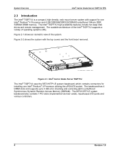
Chapter 5: Power Interconnect System Board Describes the specifications of this document. Introduction This document provides an overview of the Intel® Carrier Grade Server TIGPT1U (Telecom Industrial Grade Prescott 1U (1.75") high) and includes information on chassis hardware, cables, connectors, SE7210TP1-E System Baseboard, system boards, power subsystem, and regulatory requirements. 1.1 Document Structure and ...
Chapter 5: Power Interconnect System Board Describes the specifications of this document. Introduction This document provides an overview of the Intel® Carrier Grade Server TIGPT1U (Telecom Industrial Grade Prescott 1U (1.75") high) and includes information on chassis hardware, cables, connectors, SE7210TP1-E System Baseboard, system boards, power subsystem, and regulatory requirements. 1.1 Document Structure and ...
Product Specification
Page 12
... Computer System Interface (SCSI) disk drives. System Overview Intel® Carrier Grade Server TIGPT1U TPS 2. Intel® Carrier Grade Server TIGPT1U Feature List Feature Compact, high-density system Configuration flexibility Serviceability Availability Manageability System-level scalability Front panel Description Rack-mount server with a height of 1 U (1.75 inches) and a depth of the Intel® Carrier Grade Server TIGPT1U. Remote management Emergency management port (Serial and LAN) IPMI...
... Computer System Interface (SCSI) disk drives. System Overview Intel® Carrier Grade Server TIGPT1U TPS 2. Intel® Carrier Grade Server TIGPT1U Feature List Feature Compact, high-density system Configuration flexibility Serviceability Availability Manageability System-level scalability Front panel Description Rack-mount server with a height of 1 U (1.75 inches) and a depth of the Intel® Carrier Grade Server TIGPT1U. Remote management Emergency management port (Serial and LAN) IPMI...
Product Specification
Page 13
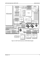
... Provides an overview and block diagram of the Intel® Carrier Grade Server TIGPT1U. Section 2.7: Specifications Summarizes the environmental and physical specifications of the Intel® Carrier Grade Server TIGPT1U. Section 2.5: Internal Chassis Features Provides an overview of the components of the Intel® Carrier Grade Server TIGPT1U. Section 2.6: Server Management Describes the server management features of the Intel® Carrier Grade Server TIGPT1U. Intel® Carrier Grade Server TIGPT1U TPS System Overview 2.2 Chapter Structure and Outline...
... Provides an overview and block diagram of the Intel® Carrier Grade Server TIGPT1U. Section 2.7: Specifications Summarizes the environmental and physical specifications of the Intel® Carrier Grade Server TIGPT1U. Section 2.5: Internal Chassis Features Provides an overview of the components of the Intel® Carrier Grade Server TIGPT1U. Section 2.6: Server Management Describes the server management features of the Intel® Carrier Grade Server TIGPT1U. Intel® Carrier Grade Server TIGPT1U TPS System Overview 2.2 Chapter Structure and Outline...
Product Specification
Page 14
... 4 DIMM slots and supports up to 4 GB error checking and correcting (ECC) unbuffered Synchronous Dynamic Random Access Memory (SDRAM). Intel® Carrier Grade Server TIGPT1U The Intel® TIGPT1U uses the SE7210TP1-E system baseboard, which contains connectors for one Intel® Pentium® 4 Processor utilizing the uPGA478 socket. The SE7210TP1-E system baseboard also contains 1 PCI slots (implemented via...
... 4 DIMM slots and supports up to 4 GB error checking and correcting (ECC) unbuffered Synchronous Dynamic Random Access Memory (SDRAM). Intel® Carrier Grade Server TIGPT1U The Intel® TIGPT1U uses the SE7210TP1-E system baseboard, which contains connectors for one Intel® Pentium® 4 Processor utilizing the uPGA478 socket. The SE7210TP1-E system baseboard also contains 1 PCI slots (implemented via...

Product Specification
Page 15
... SE7210TP1-E system baseboard is mounted horizontally toward the rear of the chassis behind the system fan array. Intel® Carrier Grade Server TIGPT1U (shown with top covers and bezel removed) A. System Memory F. Intel® Carrier Grade Server TIGPT1U TPS A BC DE F G System Overview M L H K J I . SE7210TP1-E Server Baseboard E. Power Supply B. System Fans G. Peripheral Bay (CDROM or DVD) J. Riser card assembly (full-length) D. Revision...
... SE7210TP1-E system baseboard is mounted horizontally toward the rear of the chassis behind the system fan array. Intel® Carrier Grade Server TIGPT1U (shown with top covers and bezel removed) A. System Memory F. Intel® Carrier Grade Server TIGPT1U TPS A BC DE F G System Overview M L H K J I . SE7210TP1-E Server Baseboard E. Power Supply B. System Fans G. Peripheral Bay (CDROM or DVD) J. Riser card assembly (full-length) D. Revision...

Product Specification
Page 16
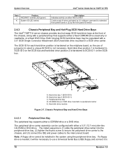
... two hot swap drive bays. The front bezel is located in the mid center and right of the Intel® Carrier Grade Server TIGPT1U with DC-input. Figure 2-3 shows a block diagram of the chassis. System Overview Intel® Carrier Grade Server TIGPT1U TPS Up to two 1.0" Ultra-320 SCSI technology hard drives can be mounted in the hot swap drive...
... two hot swap drive bays. The front bezel is located in the mid center and right of the Intel® Carrier Grade Server TIGPT1U with DC-input. Figure 2-3 shows a block diagram of the chassis. System Overview Intel® Carrier Grade Server TIGPT1U TPS Up to two 1.0" Ultra-320 SCSI technology hard drives can be mounted in the hot swap drive...
Product Specification
Page 17
... SCA Conn 80pin SCSI Hard Drive 1 Hot Plug Drive Assembly Consists of : 1. SCA SCSI Disk Drive 2. Intel® Carrier Grade Server TIGPT1U TPS System Overview 250 W Power Supply (AC-input or DC-input) LAN 2 82541 Gb E/N VGA RAGE XL Winbond W83627HF-AW Super I/O Alarm Out PS2 Keyboard/... Bus SCSI SCA Conn 80pin Sig 2x20, Pwr 1x2 1/2" CDROM/DVD SCSI SCA Conn 80pin SCSI Hard Drive 1 Hot Plug Drive Assembly Consists of : 1. Drive Carrier SCSI Hard Drive Bay 1 SCSI Hard Drive Bay 0 Figure 2-3.
... SCA Conn 80pin SCSI Hard Drive 1 Hot Plug Drive Assembly Consists of : 1. SCA SCSI Disk Drive 2. Intel® Carrier Grade Server TIGPT1U TPS System Overview 250 W Power Supply (AC-input or DC-input) LAN 2 82541 Gb E/N VGA RAGE XL Winbond W83627HF-AW Super I/O Alarm Out PS2 Keyboard/... Bus SCSI SCA Conn 80pin Sig 2x20, Pwr 1x2 1/2" CDROM/DVD SCSI SCA Conn 80pin SCSI Hard Drive 1 Hot Plug Drive Assembly Consists of : 1. Drive Carrier SCSI Hard Drive Bay 1 SCSI Hard Drive Bay 0 Figure 2-3.

Product Specification
Page 18
... the control switches and status LEDs contained on the front panel system board. Please refer to the two hot-plug hard drive bays. System Overview Intel® Carrier Grade Server TIGPT1U TPS 2.4 External Chassis Features 2.4.1 Front View of Chassis Figure 2-4 shows the front view of the system with bezel removed) 2.4.2 Front Panel The front panel...
... the control switches and status LEDs contained on the front panel system board. Please refer to the two hot-plug hard drive bays. System Overview Intel® Carrier Grade Server TIGPT1U TPS 2.4 External Chassis Features 2.4.1 Front View of Chassis Figure 2-4 shows the front view of the system with bezel removed) 2.4.2 Front Panel The front panel...

Product Specification
Page 19
...The front panel critical alarm relay will be a correctable ECC error. A minor system fault is detected by the system but in the server. When continuously lit, indicates the presence of a Major System Fault. In this case, the system can continue to operate. When continuously ...The front panel power alarm relay will be engaged. An example could be the loss of a large section of non-fatal feature reduction). Intel® Carrier Grade Server TIGPT1U TPS A B CDE F System Overview M L KJ I Main power LED (green) Description Toggles the system power Resets the system Toggles ...
...The front panel critical alarm relay will be a correctable ECC error. A minor system fault is detected by the system but in the server. When continuously lit, indicates the presence of a Major System Fault. In this case, the system can continue to operate. When continuously ...The front panel power alarm relay will be engaged. An example could be the loss of a large section of non-fatal feature reduction). Intel® Carrier Grade Server TIGPT1U TPS A B CDE F System Overview M L KJ I Main power LED (green) Description Toggles the system power Resets the system Toggles ...
Product Specification
Page 20
... drive bays may be necessary to use of the chassis, along with a 3.5" SCSI Single Connector Attachment (SCA) hard disk drive mounted in a peripheral carrier E. System Overview Intel® Carrier Grade Server TIGPT1U TPS Item J K Feature NIC0/NIC1 activity LED (green) System ID LED (white) Description Indicates activity on either NIC0 or NIC1 Continuously lit when activated...
... drive bays may be necessary to use of the chassis, along with a 3.5" SCSI Single Connector Attachment (SCA) hard disk drive mounted in a peripheral carrier E. System Overview Intel® Carrier Grade Server TIGPT1U TPS Item J K Feature NIC0/NIC1 activity LED (green) System ID LED (white) Description Indicates activity on either NIC0 or NIC1 Continuously lit when activated...

Product Specification
Page 21
... CDROM drive or DVD drive is shown in the drive carrier assembly before installing it into the system. Two screws to connect interface board to CD-ROM or DVD drive Figure 2-9. Intel® Carrier Grade Server TIGPT1U TPS System Overview the USB connection on the front of ...the unit or one of the USB connections on the back of the drive carrier assembly is installed in the following figure: 1 D 3 1 C 2 2 B...
... CDROM drive or DVD drive is shown in the drive carrier assembly before installing it into the system. Two screws to connect interface board to CD-ROM or DVD drive Figure 2-9. Intel® Carrier Grade Server TIGPT1U TPS System Overview the USB connection on the front of ...the unit or one of the USB connections on the back of the drive carrier assembly is installed in the following figure: 1 D 3 1 C 2 2 B...

Product Specification
Page 22
... disk drive position 2 is done correctly, the drive carrier will be flush with the bottom and sides of the drive, and all four mounting tabs will be installed in the hard drive bays. System Overview Intel® Carrier Grade Server TIGPT1U TPS Prior to installing the drive in the system, ...(1) the interface board is then installed in the drive carrier metal housing by holding the left side of the drive carrier in the left hand, and with the ...
... disk drive position 2 is done correctly, the drive carrier will be flush with the bottom and sides of the drive, and all four mounting tabs will be installed in the hard drive bays. System Overview Intel® Carrier Grade Server TIGPT1U TPS Prior to installing the drive in the system, ...(1) the interface board is then installed in the drive carrier metal housing by holding the left side of the drive carrier in the left hand, and with the ...

