
Product Specification
Page 3
... 3.4.2 Serial Ports 26 3.4.3 Video Port 27 3.4.4 Universal Serial Bus (USB) Interface 27 3.4.5 Ethernet Connector 28 Revision 1.0 Intel Secret iii Introduction ...1 1.1 Document Structure and Outline 1 2. Intel® Carrier Grade Server TIGPT1U TPS Table of Contents Table of Chassis 13 2.5 Internal Chassis Features 15 2.5.1 Telecom SE7210TP1-E Server Baseboard 15 2.5.2 Full-Height, Full-Length PCI Adapter Subsystem 16 2.5.3 Power Subsystem 17 2.5.4 Cooling Subsystem 18 2.6 Server Management 19 2.6.1 Baseboard Management Controller 19 2.7 Specifications 20...
... 3.4.2 Serial Ports 26 3.4.3 Video Port 27 3.4.4 Universal Serial Bus (USB) Interface 27 3.4.5 Ethernet Connector 28 Revision 1.0 Intel Secret iii Introduction ...1 1.1 Document Structure and Outline 1 2. Intel® Carrier Grade Server TIGPT1U TPS Table of Contents Table of Chassis 13 2.5 Internal Chassis Features 15 2.5.1 Telecom SE7210TP1-E Server Baseboard 15 2.5.2 Full-Height, Full-Length PCI Adapter Subsystem 16 2.5.3 Power Subsystem 17 2.5.4 Cooling Subsystem 18 2.6 Server Management 19 2.6.1 Baseboard Management Controller 19 2.7 Specifications 20...

Product Specification
Page 5
... Connector Interlocks 54 7.3.4 Signal Descriptions 54 7.4 Connector Interface 56 7.4.1 Midplane Power/Signal Connector Pinout 57 7.4.2 Midplane SCSl Connector Pinout and SCSI ID settings 57 7.5 Specifications 57 7.5.1 Electrical Specifications 57 8. Intel® Carrier Grade Server TIGPT1U TPS Table of Contents 5.2 Chapter Structure and Outline 44 5.3 Functional Description of Power Interconnect System Board 44 5.4 Connector Description 45 5.4.1 Connector Mating to the Power Supply Pinout 45 5.4.2 Connector Mating to the Extended Front Panel System Board...
... Connector Interlocks 54 7.3.4 Signal Descriptions 54 7.4 Connector Interface 56 7.4.1 Midplane Power/Signal Connector Pinout 57 7.4.2 Midplane SCSl Connector Pinout and SCSI ID settings 57 7.5 Specifications 57 7.5.1 Electrical Specifications 57 8. Intel® Carrier Grade Server TIGPT1U TPS Table of Contents 5.2 Chapter Structure and Outline 44 5.3 Functional Description of Power Interconnect System Board 44 5.4 Connector Description 45 5.4.1 Connector Mating to the Power Supply Pinout 45 5.4.2 Connector Mating to the Extended Front Panel System Board...

Product Specification
Page 7
... Layout of System 8 Figure 2-5. DC Input Terminal Block 60 Figure 8-3. Front View of Power Interconnect System Board 44 Figure 6-1. SCSI Hard Drive Carrier 13 Figure 2-12. AC Power Input Connector 29 Figure 3-4. Peripheral Drive Bay 11 Figure 2-9. Extended Front Panel Board Connector Location 36 Figure 5-1. Terminal Block Polarity 60 Revision 1.0 Intel Secret vii Intel® Carrier Grade Server TIGPT1U TPS List of Figures List of System 13 Figure 2-13. Intel® Carrier Grade Server TIGPT1U Block Diagram...
... Layout of System 8 Figure 2-5. DC Input Terminal Block 60 Figure 8-3. Front View of Power Interconnect System Board 44 Figure 6-1. SCSI Hard Drive Carrier 13 Figure 2-12. AC Power Input Connector 29 Figure 3-4. Peripheral Drive Bay 11 Figure 2-9. Extended Front Panel Board Connector Location 36 Figure 5-1. Terminal Block Polarity 60 Revision 1.0 Intel Secret vii Intel® Carrier Grade Server TIGPT1U TPS List of Figures List of System 13 Figure 2-13. Intel® Carrier Grade Server TIGPT1U Block Diagram...

Product Specification
Page 9
... 2-3. COM2: Serial Port Connector on Front Panel 26 Table 3-5. Front Panel System Status LED Description 32 Table 4-4. SCSI SMBus I /O Mapping 34 Table 4-7. Intel® Carrier Grade Server TIGPT1U TPS List of Tables List of Tables Table 2-1. Intel® Carrier Grade Server TIGPT1U Feature List 2 Table 2-2. System Features - Environmental Specifications Summary 20 Table 2-5. Keyboard/Mouse PS/2 Connector Pin Out (J9A1 25 Table 3-3. Single USB Connector 27 Table 3-7. Front Panel System Fault LED Description 33 Table 4-5. Extended Front Panel System Board Connector Information...
... 2-3. COM2: Serial Port Connector on Front Panel 26 Table 3-5. Front Panel System Status LED Description 32 Table 4-4. SCSI SMBus I /O Mapping 34 Table 4-7. Intel® Carrier Grade Server TIGPT1U TPS List of Tables List of Tables Table 2-1. Intel® Carrier Grade Server TIGPT1U Feature List 2 Table 2-2. System Features - Environmental Specifications Summary 20 Table 2-5. Keyboard/Mouse PS/2 Connector Pin Out (J9A1 25 Table 3-3. Single USB Connector 27 Table 3-7. Front Panel System Fault LED Description 33 Table 4-5. Extended Front Panel System Board Connector Information...
Product Specification
Page 12
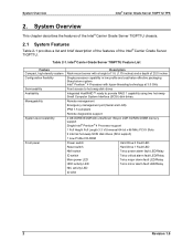
Intel® Carrier Grade Server TIGPT1U Feature List Feature Compact, high-density system Configuration flexibility Serviceability Availability Manageability System-level scalability Front panel Description Rack-mount server with hyper-threading technology at 3.0 GHz Front access to hot swap disk drives Integrated HostRAID™ ready to provide RAID 1 capability using two hot-swap Small Computer System Interface (SCSI) disk drives. Remote management Emergency management port (Serial and LAN) IPMI 1.5 compliant Remote diagnostics support 4 GB DDR333/DDR400 unbuffered 184-pin ...
Intel® Carrier Grade Server TIGPT1U Feature List Feature Compact, high-density system Configuration flexibility Serviceability Availability Manageability System-level scalability Front panel Description Rack-mount server with hyper-threading technology at 3.0 GHz Front access to hot swap disk drives Integrated HostRAID™ ready to provide RAID 1 capability using two hot-swap Small Computer System Interface (SCSI) disk drives. Remote management Emergency management port (Serial and LAN) IPMI 1.5 compliant Remote diagnostics support 4 GB DDR333/DDR400 unbuffered 184-pin ...
Product Specification
Page 14
... baseboard has 4 DIMM slots and supports up to 4 GB error checking and correcting (ECC) unbuffered Synchronous Dynamic Random Access Memory (SDRAM). Figure 2-1 shows an isometric view of operating systems (OS). Intel® Carrier Grade Server TIGPT1U The Intel® TIGPT1U uses the SE7210TP1-E system baseboard, which contains connectors for one Intel® Pentium® 4 Processor utilizing the uPGA478 socket. The Intel® TIGPT1U high availability features include hot swap disk drives and remote management.
... baseboard has 4 DIMM slots and supports up to 4 GB error checking and correcting (ECC) unbuffered Synchronous Dynamic Random Access Memory (SDRAM). Figure 2-1 shows an isometric view of operating systems (OS). Intel® Carrier Grade Server TIGPT1U The Intel® TIGPT1U uses the SE7210TP1-E system baseboard, which contains connectors for one Intel® Pentium® 4 Processor utilizing the uPGA478 socket. The Intel® TIGPT1U high availability features include hot swap disk drives and remote management.

Product Specification
Page 15
PCI card bracket (full-length) C. Front Panel LEDs and Switches K. COM2/USB Front Panel Connector L. Power Interconnect System Board The SE7210TP1-E system baseboard is mounted horizontally toward the rear of the chassis behind the system fan array. Intel® Carrier Grade Server TIGPT1U (shown with top covers and bezel removed) A. System Fans G. Power Supply B. System Memory F. Peripheral Bay (CDROM or DVD) J. Riser card assembly (full-length) D. Intel® Carrier Grade Server TIGPT1U TPS A BC DE F G System Overview M L H K J I . SE7210TP1-E Server ...
PCI card bracket (full-length) C. Front Panel LEDs and Switches K. COM2/USB Front Panel Connector L. Power Interconnect System Board The SE7210TP1-E system baseboard is mounted horizontally toward the rear of the chassis behind the system fan array. Intel® Carrier Grade Server TIGPT1U (shown with top covers and bezel removed) A. System Fans G. Power Supply B. System Memory F. Peripheral Bay (CDROM or DVD) J. Riser card assembly (full-length) D. Intel® Carrier Grade Server TIGPT1U TPS A BC DE F G System Overview M L H K J I . SE7210TP1-E Server ...

Product Specification
Page 16
... components. System Overview Intel® Carrier Grade Server TIGPT1U TPS Up to two 1.0" Ultra-320 SCSI technology hard drives can be removed to access the hot swap drive trays when installing or removing them from the hot swap drive bays. Figure 2-2 shows the location of the baseboard. The extended front panel board is located in the front left of the chassis, the power supply interface board is located in the mid...
... components. System Overview Intel® Carrier Grade Server TIGPT1U TPS Up to two 1.0" Ultra-320 SCSI technology hard drives can be removed to access the hot swap drive trays when installing or removing them from the hot swap drive bays. Figure 2-2 shows the location of the baseboard. The extended front panel board is located in the front left of the chassis, the power supply interface board is located in the mid...
Product Specification
Page 17
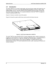
Drive Carrier SCSI SCA Conn 80pin SCSI Hard Drive 1 Hot Plug Drive Assembly Consists of : 1. Drive Carrier SCSI Hard Drive Bay 1 SCSI Hard Drive Bay 0 Figure 2-3. SCA SCSI Disk Drive 2. SCA SCSI Disk Drive 2. Intel® Carrier Grade Server TIGPT1U Block Diagram Revision 1.0 7 Intel® Carrier Grade Server TIGPT1U TPS System Overview 250 W Power Supply (AC-input or DC-input) LAN 2 82541 Gb E/N VGA RAGE XL Winbond W83627HF-AW Super I/O Alarm Out PS2 Keyboard/Mouse COM1 (Back) COM2 (Front) System Baseboard 87431 mBMC PCI Slot 1 Full...
Drive Carrier SCSI SCA Conn 80pin SCSI Hard Drive 1 Hot Plug Drive Assembly Consists of : 1. Drive Carrier SCSI Hard Drive Bay 1 SCSI Hard Drive Bay 0 Figure 2-3. SCA SCSI Disk Drive 2. SCA SCSI Disk Drive 2. Intel® Carrier Grade Server TIGPT1U Block Diagram Revision 1.0 7 Intel® Carrier Grade Server TIGPT1U TPS System Overview 250 W Power Supply (AC-input or DC-input) LAN 2 82541 Gb E/N VGA RAGE XL Winbond W83627HF-AW Super I/O Alarm Out PS2 Keyboard/Mouse COM1 (Back) COM2 (Front) System Baseboard 87431 mBMC PCI Slot 1 Full...

Product Specification
Page 18
... system. All front panel control switches and status LEDs are described in detail in Table 2-2. Please refer to the two hot-plug hard drive bays. System Overview Intel® Carrier Grade Server TIGPT1U TPS 2.4 External Chassis Features 2.4.1 Front View of Chassis Figure 2-4 shows the front view of System RJ45 COM2 and Front Panel Control Dual USB Connectors Switches and Status LEDs Peripheral Bay Drive Bay 2 Drive Bay 2 Handle Drive Bay 1 Drive Bay 1 Handle Figure...
... system. All front panel control switches and status LEDs are described in detail in Table 2-2. Please refer to the two hot-plug hard drive bays. System Overview Intel® Carrier Grade Server TIGPT1U TPS 2.4 External Chassis Features 2.4.1 Front View of Chassis Figure 2-4 shows the front view of System RJ45 COM2 and Front Panel Control Dual USB Connectors Switches and Status LEDs Peripheral Bay Drive Bay 2 Drive Bay 2 Handle Drive Bay 1 Drive Bay 1 Handle Figure...
Product Specification
Page 20
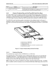
...-ROM drive or DVD drive mounted in a SCSI drive carrier. The install sequence is needed, it will be installed in the system using the peripheral drive bay. Peripheral drive bay D. Hard disk drive position 1 is hardwired to extended front panel board or (2) by the front panel ID switch 2.4.3 Chassis Peripheral Bay and Hot-Plug SCSI Hard Drive Bays The Intel® TIGPT1U server chassis provides two hot-swap SCSI hard drive bays at the front of jumper(s) to...
...-ROM drive or DVD drive mounted in a SCSI drive carrier. The install sequence is needed, it will be installed in the system using the peripheral drive bay. Peripheral drive bay D. Hard disk drive position 1 is hardwired to extended front panel board or (2) by the front panel ID switch 2.4.3 Chassis Peripheral Bay and Hot-Plug SCSI Hard Drive Bays The Intel® TIGPT1U server chassis provides two hot-swap SCSI hard drive bays at the front of jumper(s) to...

Product Specification
Page 22
... the left side of the drive carrier assembly. Ultra 320 SCSI technology (SCA interconnect) or slower hard disk drives can be installed in the right side of power. System Overview Intel® Carrier Grade Server TIGPT1U TPS Prior to installing the drive in place by latching the handle on the drive. If this is installed into the right side of the drive carrier, (2) making sure to line up to...
... the left side of the drive carrier assembly. Ultra 320 SCSI technology (SCA interconnect) or slower hard disk drives can be installed in the right side of power. System Overview Intel® Carrier Grade Server TIGPT1U TPS Prior to installing the drive in place by latching the handle on the drive. If this is installed into the right side of the drive carrier, (2) making sure to line up to...

Product Specification
Page 26
...): to run 400 MHz memory at full speed requires an Intel® Pentium® 4 Processor with 800 MHz system bus frequency. • PC2700 (333 MHz): to six system fans o Server System Infrastructure (SSI)-compliant connectors for SSI interface support: front panel, power connector o Intel® Server Management 5.8 support via the National Semiconductor* PC87431M* Baseboard Management Controller (mBMC) 2.5.2 Full-Height, Full-Length PCI Adapter Subsystem A one-slot PCI adapter assembly that is configured and installed as...
...): to run 400 MHz memory at full speed requires an Intel® Pentium® 4 Processor with 800 MHz system bus frequency. • PC2700 (333 MHz): to six system fans o Server System Infrastructure (SSI)-compliant connectors for SSI interface support: front panel, power connector o Intel® Server Management 5.8 support via the National Semiconductor* PC87431M* Baseboard Management Controller (mBMC) 2.5.2 Full-Height, Full-Length PCI Adapter Subsystem A one-slot PCI adapter assembly that is configured and installed as...

Product Specification
Page 29
... SE7210TP1-E System Baseboard components • 4 GB of SDRAM memory • Two 15,000 RPM hard drives at a maximum of 18 watts per drive • 1 PCI card at the lower fan speed settings. The firmware for the National Semiconductor* PC87431M* (mBMC) is not intended to the System Server Management External Architecture Specification for controlling system power, resets, monitoring voltages, temperatures, fans, and communicating with SIO and ADT7463 • System event...
... SE7210TP1-E System Baseboard components • 4 GB of SDRAM memory • Two 15,000 RPM hard drives at a maximum of 18 watts per drive • 1 PCI card at the lower fan speed settings. The firmware for the National Semiconductor* PC87431M* (mBMC) is not intended to the System Server Management External Architecture Specification for controlling system power, resets, monitoring voltages, temperatures, fans, and communicating with SIO and ADT7463 • System event...

Product Specification
Page 33
... Extended Front Panel Board 1x3 pwr cbl (5V) USB 2x5 2x5 Pin USB Cbl U S B C O M 2 Push Buttons Pwr|Rst NMI|ID System Fault LEDs Crt|Mjr|Mnr|Pwr Activity/ID LEDs ID|NIC|On|Disk1|Disk0 SCSI SCA Conn 80pin 1x3 Fan Fan 6 40x28 SCSI Hard Drive 1 Hot Plug Drive Assembly Consists of the boards used in the Intel® TIGPT1U. SCA SCSI Disk Drive 2. Intel® Carrier Grade Server TIGPT1U TPS Cables and Connectors 3.2 Interconnect Block Diagram Figure...
... Extended Front Panel Board 1x3 pwr cbl (5V) USB 2x5 2x5 Pin USB Cbl U S B C O M 2 Push Buttons Pwr|Rst NMI|ID System Fault LEDs Crt|Mjr|Mnr|Pwr Activity/ID LEDs ID|NIC|On|Disk1|Disk0 SCSI SCA Conn 80pin 1x3 Fan Fan 6 40x28 SCSI Hard Drive 1 Hot Plug Drive Assembly Consists of the boards used in the Intel® TIGPT1U. SCA SCSI Disk Drive 2. Intel® Carrier Grade Server TIGPT1U TPS Cables and Connectors 3.2 Interconnect Block Diagram Figure...
Product Specification
Page 35
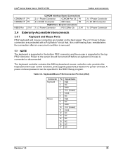
... fuse, reestablishes the connection after an overcurrent condition is removed. ✏ NOTE The keyboard is supported in the bottom PS/2 connector and the mouse is connected or disconnected. Table 3-2. The keyboard controller contains the AMI keyboard and mouse controller code, provides the keyboard and mouse control functions, and supports password protection for power-on /reset password can be turned off before a keyboard or mouse is supported in the BIOS Setup program. Keyboard/Mouse PS/2 Connector Pin Out (J9A1) Connector Keyboard Mouse Pin Signal Name 1 Data...
... fuse, reestablishes the connection after an overcurrent condition is removed. ✏ NOTE The keyboard is supported in the bottom PS/2 connector and the mouse is connected or disconnected. Table 3-2. The keyboard controller contains the AMI keyboard and mouse controller code, provides the keyboard and mouse control functions, and supports password protection for power-on /reset password can be turned off before a keyboard or mouse is supported in the BIOS Setup program. Keyboard/Mouse PS/2 Connector Pin Out (J9A1) Connector Keyboard Mouse Pin Signal Name 1 Data...
Product Specification
Page 40
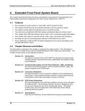
... Intel® TIGPT1U extended front panel board, showing primary components and their relationships, and physical board layout diagrams. Section 4.4: Functional Description of Front Panel Switches, LEDs, and Relays Provides a functional description of the front panel switches, LEDs, and relays contained on the extended front panel board. The information is designed for the Intel® Carrier Grade Server TIGPT1U. 4.1 Features Four switches to control power-on, reset, NMI, and the system ID LED One system ID LED...
... Intel® TIGPT1U extended front panel board, showing primary components and their relationships, and physical board layout diagrams. Section 4.4: Functional Description of Front Panel Switches, LEDs, and Relays Provides a functional description of the front panel switches, LEDs, and relays contained on the extended front panel board. The information is designed for the Intel® Carrier Grade Server TIGPT1U. 4.1 Features Four switches to control power-on, reset, NMI, and the system ID LED One system ID LED...
Product Specification
Page 63
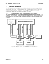
... connector (from Baseboard) Mid Plane Power/Signal Connector Internal LVD SCSI U320 12 V 5V SCSI Status Signals 12 V 5V SCSI Status Signals SCA-2 Connector Drive 2 SCA-2 Connector Drive 1 LVD Active Terminator SCSI Drive 2 SCSI Drive 1 Figure 7-1. Intel® Carrier Grade Server TIGPT1U TPS Midplane Board 7.3 Functional Description The SCSI subsystem on the midplane board is designed to give the end user support for two SCSI hot-plug hard drives. The following block diagram...
... connector (from Baseboard) Mid Plane Power/Signal Connector Internal LVD SCSI U320 12 V 5V SCSI Status Signals 12 V 5V SCSI Status Signals SCA-2 Connector Drive 2 SCA-2 Connector Drive 1 LVD Active Terminator SCSI Drive 2 SCSI Drive 1 Figure 7-1. Intel® Carrier Grade Server TIGPT1U TPS Midplane Board 7.3 Functional Description The SCSI subsystem on the midplane board is designed to give the end user support for two SCSI hot-plug hard drives. The following block diagram...

Product Specification
Page 65
... device in use of the target devices on slot. SCSI Bus Reset. SCSI Bus Select. SCSI Bus Control/Data Phase. SCSI ID. SCSI MATED. If it is from the terminator. In SE mode, these pins are bidirectional and are asserted by the controller when attempting to acknowledge the target's request for a data transfer. Drive 0 has SCSI address 0. Intel® Carrier Grade Server TIGPT1U TPS Midplane Board...
... device in use of the target devices on slot. SCSI Bus Reset. SCSI Bus Select. SCSI Bus Control/Data Phase. SCSI ID. SCSI MATED. If it is from the terminator. In SE mode, these pins are bidirectional and are asserted by the controller when attempting to acknowledge the target's request for a data transfer. Drive 0 has SCSI address 0. Intel® Carrier Grade Server TIGPT1U TPS Midplane Board...
Product Specification
Page 88
... in the Range of 9 kHz to -Ultra 320/M SCSI Single-Chip Host Adapter Specification, http://www.adaptec.com/. SCSI • Adaptec* AIC-7899* Dual-Channel PCI-to 40 GHz for EMI Testing, 1992. • CISPR 24: Information Technology Equipment - Appendix B: Reference Documents Intel® Carrier Grade Server TIGPT1U TPS Power Supply • TBD Regulatory • CISPR 22: Limits and Methods of Measurement...
... in the Range of 9 kHz to -Ultra 320/M SCSI Single-Chip Host Adapter Specification, http://www.adaptec.com/. SCSI • Adaptec* AIC-7899* Dual-Channel PCI-to 40 GHz for EMI Testing, 1992. • CISPR 24: Information Technology Equipment - Appendix B: Reference Documents Intel® Carrier Grade Server TIGPT1U TPS Power Supply • TBD Regulatory • CISPR 22: Limits and Methods of Measurement...


