User Guide
Page 3
... Grade Server TIGI2U. Intel® Carrier Grade Server TIGI2U User Guide iii Information about the specific BIOS settings and screens is for system technicians who are shipped with the board or that are responsible for troubleshooting, upgrading, and repairing this Carrier Grade Server. This manual is available in the Intel® Server Board TIGI2U Technical Product Specification. Preface Preface About this Manual Thank you for purchasing and using the utilities that may need, troubleshooting information, and instructions on how to add and replace components on Self Test) code...
... Grade Server TIGI2U. Intel® Carrier Grade Server TIGI2U User Guide iii Information about the specific BIOS settings and screens is for system technicians who are shipped with the board or that are responsible for troubleshooting, upgrading, and repairing this Carrier Grade Server. This manual is available in the Intel® Server Board TIGI2U Technical Product Specification. Preface Preface About this Manual Thank you for purchasing and using the utilities that may need, troubleshooting information, and instructions on how to add and replace components on Self Test) code...

User Guide
Page 4
... bracket for installing a CD ROM or DVD-ROM drive One 600 W SSI (Server System Infrastructure) PFC (Power Factor Correction) Four-fan assembly for cooling the processor, DIMMs (Dual Inline Memory Modules), PCI slot and other internal components One processor air duct Front panel I/O board Cables and connectors CD-ROM drive One IMM Advanced Module See the Intel® Carrier Grade Server TIGI2U Hardware Reference Guide for Intel products, see http://support.intel.com/support/motherboards/server/TIGI2U/compat...
... bracket for installing a CD ROM or DVD-ROM drive One 600 W SSI (Server System Infrastructure) PFC (Power Factor Correction) Four-fan assembly for cooling the processor, DIMMs (Dual Inline Memory Modules), PCI slot and other internal components One processor air duct Front panel I/O board Cables and connectors CD-ROM drive One IMM Advanced Module See the Intel® Carrier Grade Server TIGI2U Hardware Reference Guide for Intel products, see http://support.intel.com/support/motherboards/server/TIGI2U/compat...
User Guide
Page 5
... LAN ports are considered Type 2 or Type 4 intrabuilding ports as a reference, before working with your Carrier Grade Server Diagnostics testing software Firmware and BIOS updates System drivers Safety Information WARNING Although you need more information about this product or information about the accessories that can be used with this Carrier Grade Server, go to http://support.intel.com/support/motherboards/server/TIGI2U/index.htm In-depth technical information about the server board included with this Carrier Grade Server, including BIOS settings...
... LAN ports are considered Type 2 or Type 4 intrabuilding ports as a reference, before working with your Carrier Grade Server Diagnostics testing software Firmware and BIOS updates System drivers Safety Information WARNING Although you need more information about this product or information about the accessories that can be used with this Carrier Grade Server, go to http://support.intel.com/support/motherboards/server/TIGI2U/index.htm In-depth technical information about the server board included with this Carrier Grade Server, including BIOS settings...
User Guide
Page 6
... rack and other device installed in it must be readily accessible, and it . You must be readily accessible when installed. vi Intel® Carrier Grade Server TIGI2U User Guide See "Regulatory and Integration Information" for the server. A crush hazard exists should the rack tilt forward which may be readily accessible for disconnection then you are installed: Mains AC power disconnect: The AC power cord(s) is plugged into an...
... rack and other device installed in it must be readily accessible, and it . You must be readily accessible when installed. vi Intel® Carrier Grade Server TIGI2U User Guide See "Regulatory and Integration Information" for the server. A crush hazard exists should the rack tilt forward which may be readily accessible for disconnection then you are installed: Mains AC power disconnect: The AC power cord(s) is plugged into an...

User Guide
Page 7
... DC source must provide supplemental protection for the server. Main DC power disconnect: You are installed: Connection with a 10 in accordance with a Listed closed two-hole crimp terminal having 5/8 inch pitch. Intel® Carrier Grade Server TIGI2U User Guide vii Grounding the server: To avoid the potential for an electrical shock hazard, you must be used as controlling power to the earth ground stud(s) on a branch...
... DC source must provide supplemental protection for the server. Main DC power disconnect: You are installed: Connection with a 10 in accordance with a Listed closed two-hole crimp terminal having 5/8 inch pitch. Intel® Carrier Grade Server TIGI2U User Guide vii Grounding the server: To avoid the potential for an electrical shock hazard, you must be used as controlling power to the earth ground stud(s) on a branch...

User Guide
Page 10
... Intel® Carrier Grade Server TIGI2U Features 16 Server Platform Components 19 Server Platform Back Panel 20 Server Platform Front Panel 21 Server Platform Peripherals 22 Server Board Connector and Component Locations 23 Configuration Jumpers ...24 Front Panel IO (FPIO) System Board 25 Features ...25 FPIO SCSI Subsystem Status LEDs 25 Peripheral Bay...26 Hard Disk Drives ...26 Interconnect System (SysCon) Board 26 Power Supply ...27 System Cooling ...28 Hardware Requirements ...28 Processor ...28 Memory ...29 Platform Installations and Upgrades 33...
... Intel® Carrier Grade Server TIGI2U Features 16 Server Platform Components 19 Server Platform Back Panel 20 Server Platform Front Panel 21 Server Platform Peripherals 22 Server Board Connector and Component Locations 23 Configuration Jumpers ...24 Front Panel IO (FPIO) System Board 25 Features ...25 FPIO SCSI Subsystem Status LEDs 25 Peripheral Bay...26 Hard Disk Drives ...26 Interconnect System (SysCon) Board 26 Power Supply ...27 System Cooling ...28 Hardware Requirements ...28 Processor ...28 Memory ...29 Platform Installations and Upgrades 33...
User Guide
Page 11
... You Cannot Access Setup 82 Setup Menus ...82 Upgrading the BIOS ...84 Preparing for the Upgrade 84 Upgrading the BIOS 85 Clearing the Password ...85 Clearing the CMOS ...86 Troubleshooting 87 Resetting the System ...87 Problems following Initial System Installation 88 First Steps Checklist 88 Hardware Diagnostic Testing 89 Verifying Proper Operation of Key System Lights 89 Confirming Loading of the Operating System 90 Specific Problems and Corrective Actions 90 Power Light Does Not Light 90 Intel® Carrier Grade Server TIGI2U User Guide 11
... You Cannot Access Setup 82 Setup Menus ...82 Upgrading the BIOS ...84 Preparing for the Upgrade 84 Upgrading the BIOS 85 Clearing the Password ...85 Clearing the CMOS ...86 Troubleshooting 87 Resetting the System ...87 Problems following Initial System Installation 88 First Steps Checklist 88 Hardware Diagnostic Testing 89 Verifying Proper Operation of Key System Lights 89 Confirming Loading of the Operating System 90 Specific Problems and Corrective Actions 90 Power Light Does Not Light 90 Intel® Carrier Grade Server TIGI2U User Guide 11
User Guide
Page 12
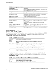
... Limitations of Liability 112 How to a Server 92 Problems with Network 93 System Boots when Installing PCI Card 93 Problems with Newly Installed Application Software 94 Problems with Application Software that Ran Correctly Earlier 94 Devices are not Recognized under Device Manager (Windows* Operating System) ..95 Hard Drive(s) are not Recognized 95 Bootable CD-ROM Is Not Detected 95 LED Information...96 BIOS Error Messages ...97 BIOS POST Beep Codes 98 Regulatory and Certification Information 100...
... Limitations of Liability 112 How to a Server 92 Problems with Network 93 System Boots when Installing PCI Card 93 Problems with Newly Installed Application Software 94 Problems with Application Software that Ran Correctly Earlier 94 Devices are not Recognized under Device Manager (Windows* Operating System) ..95 Hard Drive(s) are not Recognized 95 Bootable CD-ROM Is Not Detected 95 LED Information...96 BIOS Error Messages ...97 BIOS POST Beep Codes 98 Regulatory and Certification Information 100...

User Guide
Page 13
.... Installing the Processor in the Processor Socket 44 Figure 20. Inserting the Front Panel Board 64 Figure 42. Inserting Hard Disk Drive Assembly into Riser 52 Figure 29. Removing the Full Height PCI Riser Board 67 Figure 45. Installing Memory DIMMs 41 Figure 17. Installing the Power Supply 56 Figure 34. Removing the Serial/Alarms Cable Threaded Standoffs 71 Intel® Carrier Grade Server TIGI2U User Guide 13 Removing a Full Height PCI Card 54 Figure 32. Removing the Front Panel Board 62...
.... Installing the Processor in the Processor Socket 44 Figure 20. Inserting the Front Panel Board 64 Figure 42. Inserting Hard Disk Drive Assembly into Riser 52 Figure 29. Removing the Full Height PCI Riser Board 67 Figure 45. Installing Memory DIMMs 41 Figure 17. Installing the Power Supply 56 Figure 34. Removing the Serial/Alarms Cable Threaded Standoffs 71 Intel® Carrier Grade Server TIGI2U User Guide 13 Removing a Full Height PCI Card 54 Figure 32. Removing the Front Panel Board 62...

User Guide
Page 17
...; processors with an 800 MT/s MHz front side bus at frequency 3.2 GHz with 2MB cache. USB 2.0 compliant with 8MB SDRAM Continued Intel® Carrier Grade Server TIGI2U User Guide 17 On-board ATI* RAGE XL video controller with less than ten feet of external cable U320 high-density 80-pin SCSI connector (channel B) Internal connections: Add-in Card Video Two USB port headers, each of which supports two USB 2.0 ports One DH10 Serial A header...
...; processors with an 800 MT/s MHz front side bus at frequency 3.2 GHz with 2MB cache. USB 2.0 compliant with 8MB SDRAM Continued Intel® Carrier Grade Server TIGI2U User Guide 17 On-board ATI* RAGE XL video controller with less than ten feet of external cable U320 high-density 80-pin SCSI connector (channel B) Internal connections: Add-in Card Video Two USB port headers, each of which supports two USB 2.0 ports One DH10 Serial A header...

User Guide
Page 18
... Zero-channel RAID supporting the RUBI-2 specification Dual Intel® 82546GB 10/100/1000 NICs Two 80mm x 38mm fans Two 40mm x 28mm fans On-board Platform Instrumentation using the National Semiconductor* PC87431M mini-Baseboard Management Controller (mBMC) (Default). Support for Intel® Server Management 8.x Intel® Light-Guided Diagnostics on all field replaceable units (FRUs) Intel® Server Management 5.8 support Telco Alarm Manager (TAM) 18 Intel® Carrier Grade Server TIGI2U User Guide Advanced Edition or...
... Zero-channel RAID supporting the RUBI-2 specification Dual Intel® 82546GB 10/100/1000 NICs Two 80mm x 38mm fans Two 40mm x 28mm fans On-board Platform Instrumentation using the National Semiconductor* PC87431M mini-Baseboard Management Controller (mBMC) (Default). Support for Intel® Server Management 8.x Intel® Light-Guided Diagnostics on all field replaceable units (FRUs) Intel® Server Management 5.8 support Telco Alarm Manager (TAM) 18 Intel® Carrier Grade Server TIGI2U User Guide Advanced Edition or...
User Guide
Page 48
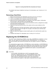
... hard drive. 6. Replacing the CD-ROM Drive Your Intel® Carrier Grade Server TIGI2U comes with a DVD-ROM drive. Both the blind-mate CD-ROM drive carrier assembly and the blind-mate DVD-ROM drive carrier assembly can replace the CD-ROM drive with a CD-ROM drive installed in an anti-static bag. 5. (optional) Place the plastic retention device into the chassis. After the drive carrier assembly is used to secure it . As an option, you removed from the chassis. 4. Install the front bezel. Remove...
... hard drive. 6. Replacing the CD-ROM Drive Your Intel® Carrier Grade Server TIGI2U comes with a DVD-ROM drive. Both the blind-mate CD-ROM drive carrier assembly and the blind-mate DVD-ROM drive carrier assembly can replace the CD-ROM drive with a CD-ROM drive installed in an anti-static bag. 5. (optional) Place the plastic retention device into the chassis. After the drive carrier assembly is used to secure it . As an option, you removed from the chassis. 4. Install the front bezel. Remove...

User Guide
Page 61
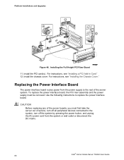
...; Power supply Power distribution board Light pipe Use the instructions below to the controls at the front of the server boards, you must be removed: All cable connections on the Front Panel I/O Board and selected connections from the system or wall outlet or disconnect the DC mains. Remove the chassis cover. For instructions, see "Removing the Chassis Cover." 3. Remove the four-fan assembly. Intel® Carrier Grade Server TIGI2U User Guide 61 Remove the processor air duct. Remove the power interface board...
...; Power supply Power distribution board Light pipe Use the instructions below to the controls at the front of the server boards, you must be removed: All cable connections on the Front Panel I/O Board and selected connections from the system or wall outlet or disconnect the DC mains. Remove the chassis cover. For instructions, see "Removing the Chassis Cover." 3. Remove the four-fan assembly. Intel® Carrier Grade Server TIGI2U User Guide 61 Remove the processor air duct. Remove the power interface board...
User Guide
Page 68
...; Carrier Grade Server TIGI2U User Guide Install the chassis cover. For instructions, see "Installing a PCI Add-in Card." 12. To replace the power interface board, the PCI riser assembly and the power supply must first take the server out of service, turn off all peripheral devices connected to the system, turn off the system by pressing the power button, and unplug the AC power cord from the power supply to replace the power interface board. CAUTION Before replacing any of the server system. Use the following instructions...
...; Carrier Grade Server TIGI2U User Guide Install the chassis cover. For instructions, see "Installing a PCI Add-in Card." 12. To replace the power interface board, the PCI riser assembly and the power supply must first take the server out of service, turn off all peripheral devices connected to the system, turn off the system by pressing the power button, and unplug the AC power cord from the power supply to replace the power interface board. CAUTION Before replacing any of the server system. Use the following instructions...
User Guide
Page 88
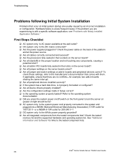
... devices installed correctly? If the system has a hard disk drive, is a less frequent cause. Hardware failure is it properly formatted or configured? Are all device drivers properly installed? Are the configuration settings made in boards sharing the same interrupt. Are all jumper and switch settings on light should be lit)? AC system only: Is the system power cord properly connected to the tested component lists. 88 Intel® Carrier Grade Server TIGI2U User Guide...
... devices installed correctly? If the system has a hard disk drive, is a less frequent cause. Hardware failure is it properly formatted or configured? Are all device drivers properly installed? Are the configuration settings made in boards sharing the same interrupt. Are all jumper and switch settings on light should be lit)? AC system only: Is the system power cord properly connected to the tested component lists. 88 Intel® Carrier Grade Server TIGI2U User Guide...
User Guide
Page 89
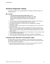
Turn on the system. Intel® Carrier Grade Server TIGI2U User Guide 89 Failure to do so can cause permanent damage to identifying a hardware problem and locating its activity light should turn off the system and all external peripheral devices. As each mass storage device installed in the CD-ROM or DVD-ROM drive. 6. Check for the keyboard and the video monitor. 2. Turn off the system and any peripheral cables from the system, except for the following: ...
Turn on the system. Intel® Carrier Grade Server TIGI2U User Guide 89 Failure to do so can cause permanent damage to identifying a hardware problem and locating its activity light should turn off the system and all external peripheral devices. As each mass storage device installed in the CD-ROM or DVD-ROM drive. 6. Check for the keyboard and the video monitor. 2. Turn off the system and any peripheral cables from the system, except for the following: ...

User Guide
Page 93
... the other PCI drivers. Troubleshooting Problems with Network The server hangs when the drivers are loaded. Certain drivers may require interrupts that came with your PCI card(s) for a link to the port from the server. Intel® Carrier Grade Server TIGI2U User Guide 93 Delete and then reinstall the drivers. Run the diagnostics. See the documentation that are not shared with other adapter supports shared interrupts. The add-in your operating system supports shared interrupts...
... the other PCI drivers. Troubleshooting Problems with Network The server hangs when the drivers are loaded. Certain drivers may require interrupts that came with your PCI card(s) for a link to the port from the server. Intel® Carrier Grade Server TIGI2U User Guide 93 Delete and then reinstall the drivers. Run the diagnostics. See the documentation that are not shared with other adapter supports shared interrupts. The add-in your operating system supports shared interrupts...
User Guide
Page 94
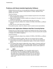
... usually related to install a surge suppressor between the power outlet and the system power cord. 94 Intel® Carrier Grade Server TIGI2U User Guide Troubleshooting Problems with Application Software that Ran Correctly Earlier Problems that occur after the system hardware and software have occurred, reload the software and try a different diskette. Make sure the correct device drivers installed. Faulty equipment is unlikely, especially if other random component failures. If you...
... usually related to install a surge suppressor between the power outlet and the system power cord. 94 Intel® Carrier Grade Server TIGI2U User Guide Troubleshooting Problems with Application Software that Ran Correctly Earlier Problems that occur after the system hardware and software have occurred, reload the software and try a different diskette. Make sure the correct device drivers installed. Faulty equipment is unlikely, especially if other random component failures. If you...
User Guide
Page 97
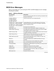
... or the battery has failed. CMOS Settings Wrong CMOS values are invalid. KB/Interface Error Keyboard interface test failed. Could not read /write test of DMA (Direct Memory Access) controller. Check Setup to protected mode during the POST, the BIOS displays an error message describing the problem. CMOS memory may be updated. Run Setup to access diskette drive controller. Update OK! continued Intel® Carrier Grade Server TIGI2U User Guide 97 Replace the battery soon. Keyboard Error Error in CMOS are not the same as the last boot. The display type is...
... or the battery has failed. CMOS Settings Wrong CMOS values are invalid. KB/Interface Error Keyboard interface test failed. Could not read /write test of DMA (Direct Memory Access) controller. Check Setup to protected mode during the POST, the BIOS displays an error message describing the problem. CMOS memory may be updated. Run Setup to access diskette drive controller. Update OK! continued Intel® Carrier Grade Server TIGI2U User Guide 97 Replace the battery soon. Keyboard Error Error in CMOS are not the same as the last boot. The display type is...
User Guide
Page 98
... BIOS uses these beep codes to boot. Table 8. Reseat or replace the failed processor. 98 Intel® Carrier Grade Server TIGI2U User Guide A parity error occurred on -board video is followed by an address. This error is cleared. Remove all error conditions are provided if an Intel® Management Module is installed. Memory size has changed since the last boot. CMOS is ignored and NVRAM is followed by an address. The Intel Management Modules provide the following additional beep codes. Troubleshooting BIOS Error Messages (continued) Error...
... BIOS uses these beep codes to boot. Table 8. Reseat or replace the failed processor. 98 Intel® Carrier Grade Server TIGI2U User Guide A parity error occurred on -board video is followed by an address. This error is cleared. Remove all error conditions are provided if an Intel® Management Module is installed. Memory size has changed since the last boot. CMOS is ignored and NVRAM is followed by an address. The Intel Management Modules provide the following additional beep codes. Troubleshooting BIOS Error Messages (continued) Error...


