Product Specification
Page 2
..., completeness or usefulness of their respective owners. Intel products are not intended for the products referenced herein, Intel assumes no commitment to update the information contained in this document, and Intel reserves the right to make changes to this document...use in this document may cause the product to obtain the latest specifications and before placing your product order. MMX is a registered trademark of the Intel® LB440GX 2U Rack Server Chassis Technical Product Specification (Part #245251-001) Rev 0.9 Revisions Rev 1.0 Legal and Trademark Review...
..., completeness or usefulness of their respective owners. Intel products are not intended for the products referenced herein, Intel assumes no commitment to update the information contained in this document, and Intel reserves the right to make changes to this document...use in this document may cause the product to obtain the latest specifications and before placing your product order. MMX is a registered trademark of the Intel® LB440GX 2U Rack Server Chassis Technical Product Specification (Part #245251-001) Rev 0.9 Revisions Rev 1.0 Legal and Trademark Review...
Product Specification
Page 3
Intel© LB440GX 2U Rack Server Chassis TPS Rev 1.0 Reference Documents § Intel® L440GX+ Technical Product Specification (TPS) Rev 1.0 § Power Supply, 300W, 5 Output, with PFC Rev 2.0 § Entry-Level Electronics-Bay Specification Rev 0.90 § ATX Specification Version 2.03 § SCSI Accessed Fault-Tolerant Enclosures Interface Specification, © Conner Peripherals and Intel Corporation, Revision 1.00, October 17, 1995 § SCSI Parallel Interface-2, draft proposal revision 20a iii
Intel© LB440GX 2U Rack Server Chassis TPS Rev 1.0 Reference Documents § Intel® L440GX+ Technical Product Specification (TPS) Rev 1.0 § Power Supply, 300W, 5 Output, with PFC Rev 2.0 § Entry-Level Electronics-Bay Specification Rev 0.90 § ATX Specification Version 2.03 § SCSI Accessed Fault-Tolerant Enclosures Interface Specification, © Conner Peripherals and Intel Corporation, Revision 1.00, October 17, 1995 § SCSI Parallel Interface-2, draft proposal revision 20a iii
Product Specification
Page 4
...-SWAP DRIVE BAYS ...8 6 FRONT PANEL...9 7 HOT-SWAP SCSI SUBSYSTEM...10 7.1 SUBSYSTEM PURPOSE ...10 7.2 ABSTRACT...10 7.3 HOT-SWAP BACKPLANE BOARD LAYOUT 11 7.3.1 Configuration Options ...11 7.4 FUNCTIONAL DESCRIPTION ...12 7.4.1 68 pin LVD high density Hot-Swap Connectors 12 7.4.2 SCSI Interface ...12 8 DUAL-SLOT PCI RISER ...13 9 CHASSIS INTERCONNECTION ...13 9.1 CHASSIS INTERNAL CABLES ...13 9.2 CONNECTOR INTERFACES...14 9.2.1 Hot-Swap Backplane and Peripheral Power Connectors 14 10 SUPPORTED INTEL SERVER BOARDS 15 10.1 INTEL®...
...-SWAP DRIVE BAYS ...8 6 FRONT PANEL...9 7 HOT-SWAP SCSI SUBSYSTEM...10 7.1 SUBSYSTEM PURPOSE ...10 7.2 ABSTRACT...10 7.3 HOT-SWAP BACKPLANE BOARD LAYOUT 11 7.3.1 Configuration Options ...11 7.4 FUNCTIONAL DESCRIPTION ...12 7.4.1 68 pin LVD high density Hot-Swap Connectors 12 7.4.2 SCSI Interface ...12 8 DUAL-SLOT PCI RISER ...13 9 CHASSIS INTERCONNECTION ...13 9.1 CHASSIS INTERNAL CABLES ...13 9.2 CONNECTOR INTERFACES...14 9.2.1 Hot-Swap Backplane and Peripheral Power Connectors 14 10 SUPPORTED INTEL SERVER BOARDS 15 10.1 INTEL®...
Product Specification
Page 5
... ENVIRONMENTAL TESTING ...20 13 RELIABILITY, SERVICEABILITY, AND AVAILABILITY 21 13.1 MEAN-TIME-BETWEEN-FAILURE (MTBF 21 13.2 SERVICEABILITY...21 Figures FIGURE 1. ACTIVE PCI RISER BLOCK DIAGRAM 13 FIGURE 9. AUX ATX POWER CONNECTOR...6 TABLE 5. PIN TYPES ...14 TABLE 9. ISOMETRIC VIEW WITHOUT TOP COVER 3 FIGURE 4. 80MM SYSTEM FAN...7 FIGURE 5. PERIPHERAL POWER CONNECTOR...14 Tables TABLE 1. PERIPHERAL POWER CONNECTOR...6 TABLE 6. FRONT PANEL AND FUNCTIONS ...9 FIGURE 6. PERIPHERAL POWER CONNECTORS ...14 TABLE 10. POWER SUPPLY OUTPUT...
... ENVIRONMENTAL TESTING ...20 13 RELIABILITY, SERVICEABILITY, AND AVAILABILITY 21 13.1 MEAN-TIME-BETWEEN-FAILURE (MTBF 21 13.2 SERVICEABILITY...21 Figures FIGURE 1. ACTIVE PCI RISER BLOCK DIAGRAM 13 FIGURE 9. AUX ATX POWER CONNECTOR...6 TABLE 5. PIN TYPES ...14 TABLE 9. ISOMETRIC VIEW WITHOUT TOP COVER 3 FIGURE 4. 80MM SYSTEM FAN...7 FIGURE 5. PERIPHERAL POWER CONNECTOR...14 Tables TABLE 1. PERIPHERAL POWER CONNECTOR...6 TABLE 6. FRONT PANEL AND FUNCTIONS ...9 FIGURE 6. PERIPHERAL POWER CONNECTORS ...14 TABLE 10. POWER SUPPLY OUTPUT...
Product Specification
Page 6
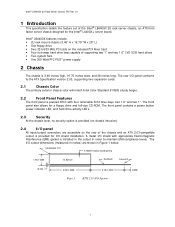
... panel also allows for the Intel® L440GX+ server board. The rear I /O shield with appropriate Electromagnetic Interference (EMI) gasket is installed in the cutout in Figure 1 below. The front panel contains a power button power indicator LED, and hard drive activity LED's. 2.3 Security At the chassis level, no security option is 3.46 inches high, 16.75 inches wide, and 28 inches long. Intel® LB440GX features include: • 2U...
... panel also allows for the Intel® L440GX+ server board. The rear I /O shield with appropriate Electromagnetic Interference (EMI) gasket is installed in the cutout in Figure 1 below. The front panel contains a power button power indicator LED, and hard drive activity LED's. 2.3 Security At the chassis level, no security option is 3.46 inches high, 16.75 inches wide, and 28 inches long. Intel® LB440GX features include: • 2U...

Product Specification
Page 7
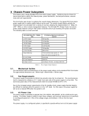
Front and Rear Chassis Views 2 Intel© LB440GX 2U Rack Server Chassis TPS Rev 1.0 2.5 Chassis Views Floppy Drive Power Switch and Drive LEDs CD-ROM Drive Bay Two 1" Hot-swap Drive Bays Two 1.6" Hot-swap Drive Bays Two PCI Bays Exhaust Grill I/O Panel: Keyboard, Mouse, Parallel Port, 2 Serial Ports, LAN, 2 USB Ports, and Video Figure 2.
Front and Rear Chassis Views 2 Intel© LB440GX 2U Rack Server Chassis TPS Rev 1.0 2.5 Chassis Views Floppy Drive Power Switch and Drive LEDs CD-ROM Drive Bay Two 1" Hot-swap Drive Bays Two 1.6" Hot-swap Drive Bays Two PCI Bays Exhaust Grill I/O Panel: Keyboard, Mouse, Parallel Port, 2 Serial Ports, LAN, 2 USB Ports, and Video Figure 2.
Product Specification
Page 9
... 23°C ± 2°C. The remote enable feature permits the chassis power to optimize the overall chassis dimensions. Intel© LB440GX 2U Rack Server Chassis TPS Rev 1.0 3 Chassis Power Subsystem This chassis uses a single standard PS/2 form factor power supply. The typical PS/2 form factor power supply with a remote enable feature can be chosen for future board sets to satisfy the chassis power, power distribution, thermal performance, acoustic noise...
... 23°C ± 2°C. The remote enable feature permits the chassis power to optimize the overall chassis dimensions. Intel© LB440GX 2U Rack Server Chassis TPS Rev 1.0 3 Chassis Power Subsystem This chassis uses a single standard PS/2 form factor power supply. The typical PS/2 form factor power supply with a remote enable feature can be chosen for future board sets to satisfy the chassis power, power distribution, thermal performance, acoustic noise...

Product Specification
Page 10
Intel© LB440GX 2U Rack Server Chassis TPS Rev 1.0 output load, nominal input voltage, with line source interruptions not to exceed one period of up to the board. Additionally, the chassis will not be obtained in ANSI/IEEE STD C62.45-1992. 3.4 Power Supply Connector Pin Assignments 3.4.1 P1 Main Power Connector Housing: 24-pin Molex* 39-01-2240, Contact: Molex 39-00-0038...
Intel© LB440GX 2U Rack Server Chassis TPS Rev 1.0 output load, nominal input voltage, with line source interruptions not to exceed one period of up to the board. Additionally, the chassis will not be obtained in ANSI/IEEE STD C62.45-1992. 3.4 Power Supply Connector Pin Assignments 3.4.1 P1 Main Power Connector Housing: 24-pin Molex* 39-01-2240, Contact: Molex 39-00-0038...

Product Specification
Page 11
... detailed specification on the power supply, see document 719680, the specification for the 300-Watt power supply with a single power supply. Floppy Drive Power Connector 3.5 Power Supply/Chassis Configuration The Intel® LB440GX 2U rack server platform can only be configured with PFC. 6 Peripheral Power Connector 3.4.4 P9 Floppy Drive Power Connector Housing: Amp 171822-4 Pin Signal 18 AWG Color 1 +5VDC Red 2 COM Black 3 COM Black 4 +12VDC Yellow Table 6. Intel© LB440GX 2U Rack Server Chassis TPS Rev 1.0 3.4.2 P10 ATX Aux Power Connector Housing: 6-pin Molex...
... detailed specification on the power supply, see document 719680, the specification for the 300-Watt power supply with a single power supply. Floppy Drive Power Connector 3.5 Power Supply/Chassis Configuration The Intel® LB440GX 2U rack server platform can only be configured with PFC. 6 Peripheral Power Connector 3.4.4 P9 Floppy Drive Power Connector Housing: Amp 171822-4 Pin Signal 18 AWG Color 1 +5VDC Red 2 COM Black 3 COM Black 4 +12VDC Yellow Table 6. Intel© LB440GX 2U Rack Server Chassis TPS Rev 1.0 3.4.2 P10 ATX Aux Power Connector Housing: 6-pin Molex...
Product Specification
Page 12
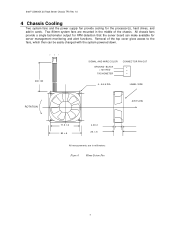
... middle of the top cover gives access to the fans, which then can make available for the processor(s), hard drives, and add-in millimeters Figure 4. 80mm System Fan 7 All chassis fans provide a single tachometer output for RPM detection that the server board can be easily changed with the system powered down. 3 2 1 230 ±30 SIGNAL AND WIRE COLOR GROUND BLACK +12V RED TACHOMETER CONNECTOR PIN OUT 1 2 3 4.- Φ4.5 DIA...
... middle of the top cover gives access to the fans, which then can make available for the processor(s), hard drives, and add-in millimeters Figure 4. 80mm System Fan 7 All chassis fans provide a single tachometer output for RPM detection that the server board can be easily changed with the system powered down. 3 2 1 230 ±30 SIGNAL AND WIRE COLOR GROUND BLACK +12V RED TACHOMETER CONNECTOR PIN OUT 1 2 3 4.- Φ4.5 DIA...
Product Specification
Page 13
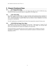
... of specific hard drives must be installed on cooling capabilities, the maximum recommended power per device is 17W. Four low-cost SECC carriers are accessible from the front of the chassis. Intel© LB440GX 2U Rack Server Chassis TPS Rev 1.0 5 Chassis Peripheral Bays 5.1 3.5" Floppy Drive Bay The chassis provides for replacement of the floppy drive. 5.2 5.25" Drive Bay The chassis supports one half-height (1.6" high) removable media peripheral devices...
... of specific hard drives must be installed on cooling capabilities, the maximum recommended power per device is 17W. Four low-cost SECC carriers are accessible from the front of the chassis. Intel© LB440GX 2U Rack Server Chassis TPS Rev 1.0 5 Chassis Peripheral Bays 5.1 3.5" Floppy Drive Bay The chassis provides for replacement of the floppy drive. 5.2 5.25" Drive Bay The chassis supports one half-height (1.6" high) removable media peripheral devices...
Product Specification
Page 14
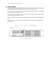
Intel© LB440GX 2U Rack Server Chassis TPS Rev 1.0 6 Front Panel The front panel board includes the Power On/Off button, a green Power On LED, four green hard drive activity LED's (not drive failures), which are visible through the front inlay. A two-pin connector is provided on the front panel board for connection to the baseboard for the power switch. Front Panel and Functions 9 A four-pin connector is provided on the front panel board for connection to the baseboard for...
Intel© LB440GX 2U Rack Server Chassis TPS Rev 1.0 6 Front Panel The front panel board includes the Power On/Off button, a green Power On LED, four green hard drive activity LED's (not drive failures), which are visible through the front inlay. A two-pin connector is provided on the front panel board for connection to the baseboard for the power switch. Front Panel and Functions 9 A four-pin connector is provided on the front panel board for connection to the baseboard for...
Product Specification
Page 15
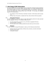
... dual mode LVD operation, compliant with Fast, Ultra and Ultra-2 SCSI bus operation. 7.1 Subsystem Purpose The Intel® LB440GX 2U rack server chassis hot-swap SCSI backplane performs the tasks associated with Ultra-2 high density LVD 68 pin drive connectors, and active terminators § SCSI drive power control § Configuration jumpers 10 The backplanes are then daisy chained with a standard 68-pin Ultra-2 SCSI cable. Each backplane supports two...
... dual mode LVD operation, compliant with Fast, Ultra and Ultra-2 SCSI bus operation. 7.1 Subsystem Purpose The Intel® LB440GX 2U rack server chassis hot-swap SCSI backplane performs the tasks associated with Ultra-2 high density LVD 68 pin drive connectors, and active terminators § SCSI drive power control § Configuration jumpers 10 The backplanes are then daisy chained with a standard 68-pin Ultra-2 SCSI cable. Each backplane supports two...
Product Specification
Page 16
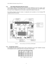
... each drive. The following table lists all possible SCSI ID switch configurations of the Intel® LB440GX hot-swap SCSI backplane and the resulting SCSI ID for the position of the Intel® LB440GX 2U rack server chassis. As a result, server management will not be able to determine the status of components and connectors on the hot-swap SCSI backplane printed circuit board. DISK POWER CONNECTOR 68Pin...
... each drive. The following table lists all possible SCSI ID switch configurations of the Intel® LB440GX hot-swap SCSI backplane and the resulting SCSI ID for the position of the Intel® LB440GX 2U rack server chassis. As a result, server management will not be able to determine the status of components and connectors on the hot-swap SCSI backplane printed circuit board. DISK POWER CONNECTOR 68Pin...
Product Specification
Page 17
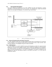
... connectors provide power and SCSI signals using two DIP-switches located on the backplanes by using a single connector. Hot Swap SCSI Backplane Block Diagram 7.4.1 68 pin LVD high density Hot-Swap Connectors The Intel® LB440GX contains two hot swap backplane boards with two high-density LVD connectors on . After powering on, the Altera EPLD detects the presence of the disks is configured on the boards. Intel© LB440GX 2U Rack Server...
... connectors provide power and SCSI signals using two DIP-switches located on the backplanes by using a single connector. Hot Swap SCSI Backplane Block Diagram 7.4.1 68 pin LVD high density Hot-Swap Connectors The Intel® LB440GX contains two hot swap backplane boards with two high-density LVD connectors on . After powering on, the Altera EPLD detects the presence of the disks is configured on the boards. Intel© LB440GX 2U Rack Server...
Product Specification
Page 18
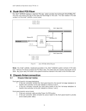
P_INT_B Intel© LB440GX 2U Rack Server Chassis TPS Rev 1.0 8 Dual-Slot PCI Riser The Intel® LB440GX employs a dual-slot PCI riser, which provides two full-length 32-bit/33Mhz PCI. The riser resides in PCI slot number 5 of the Intel® L440GX+ server board. The riser is an active riser due to the extra PCI Bus Bridge on the card.
P_INT_B Intel© LB440GX 2U Rack Server Chassis TPS Rev 1.0 8 Dual-Slot PCI Riser The Intel® LB440GX employs a dual-slot PCI riser, which provides two full-length 32-bit/33Mhz PCI. The riser resides in PCI slot number 5 of the Intel® L440GX+ server board. The riser is an active riser due to the extra PCI Bus Bridge on the card.

Product Specification
Page 19
... and hot-swap SCSI devices. 9.2 Connector Interfaces Each pin is shown below. Intel© LB440GX 2U Rack Server Chassis TPS Rev 1.0 Server board to hot-swap backplanes § An Ultra-2 SCSI cable (68-pin) is provided to interface from the installed server board to the two hot-swap backplanes. § Two high-density 68-pin connectors in the following table. Figure 9. Type PWR I/O O I O/C O/D Description Power connection (power or ground) Bi...
... and hot-swap SCSI devices. 9.2 Connector Interfaces Each pin is shown below. Intel© LB440GX 2U Rack Server Chassis TPS Rev 1.0 Server board to hot-swap backplanes § An Ultra-2 SCSI cable (68-pin) is provided to interface from the installed server board to the two hot-swap backplanes. § Two high-density 68-pin connectors in the following table. Figure 9. Type PWR I/O O I O/C O/D Description Power connection (power or ground) Bi...
Product Specification
Page 20
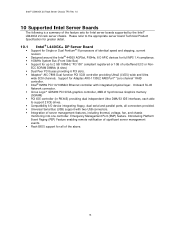
...® II processors of identical speed and stepping, current revision Designed around the Intel® 440GX AGPSet, PIIX4e, I /O device integrating floppy, dual serial and parallel ports, all of the above. 15 Integration of Synchronous Graphics memory (SGRAM) PCI IDE controller (in PIIX4E) providing dual independent Ultra DMA/33 IDE interfaces, each able to support 2 IDE drives. Intel© LB440GX 2U Rack Server Chassis TPS Rev 1.0 10 Supported Intel Server Boards The following...
...® II processors of identical speed and stepping, current revision Designed around the Intel® 440GX AGPSet, PIIX4e, I /O device integrating floppy, dual serial and parallel ports, all of the above. 15 Integration of Synchronous Graphics memory (SGRAM) PCI IDE controller (in PIIX4E) providing dual independent Ultra DMA/33 IDE interfaces, each able to support 2 IDE drives. Intel© LB440GX 2U Rack Server Chassis TPS Rev 1.0 10 Supported Intel Server Boards The following...

Product Specification
Page 23
...installation. This equipment generates, uses, and can be determined by the grantee of this equipment in accordance with the instructions, may cause harmful interference to radio communications. Any changes or modifications not expressly approved by turning the equipment off and on; In this configuration, operation of this device could void the user's authority to operate... for a Class B digital device, pursuant to Part 15 of the FCC Rules. All cables used in a residential area is likely to cause harmful interference. 18 Intel© LB440GX 2U Rack Server Chassis TPS Rev 1.0 11.1.3...
...installation. This equipment generates, uses, and can be determined by the grantee of this equipment in accordance with the instructions, may cause harmful interference to radio communications. Any changes or modifications not expressly approved by turning the equipment off and on; In this configuration, operation of this device could void the user's authority to operate... for a Class B digital device, pursuant to Part 15 of the FCC Rules. All cables used in a residential area is likely to cause harmful interference. 18 Intel© LB440GX 2U Rack Server Chassis TPS Rev 1.0 11.1.3...

Product Specification
Page 26
... Mean Time To Repair (MTTR) of the system is 30 minutes including diagnosis of this goal, the system enclosure and hardware have been designed to be provided in a future revision of the system problem. Remove cover Remove and replace hard disk drive 1 minute 1 minute Remove and replace 5 ¼ peripheral device Remove and replace power supply Remove and replace rear drive bay fans Remove and replace front system fan Remove and replace expansion board Remove and replace front panel board Remove and replace baseboard (with...
... Mean Time To Repair (MTTR) of the system is 30 minutes including diagnosis of this goal, the system enclosure and hardware have been designed to be provided in a future revision of the system problem. Remove cover Remove and replace hard disk drive 1 minute 1 minute Remove and replace 5 ¼ peripheral device Remove and replace power supply Remove and replace rear drive bay fans Remove and replace front system fan Remove and replace expansion board Remove and replace front panel board Remove and replace baseboard (with...


