Product Guide
Page 1
Intel® Server Board SHG2 Product Guide A Guide for Technically Qualified Assemblers of Intel® Identified Subassemblies/Products Order Number: A90327-003
Intel® Server Board SHG2 Product Guide A Guide for Technically Qualified Assemblers of Intel® Identified Subassemblies/Products Order Number: A90327-003
Product Guide
Page 3
Intel® SC5200 Base Chassis 36 Cable Routing - Contents 1 Description Server Board Features ...9 Back Panel Connectors 10 Server Board Connector and Component Locations 11 Processor ...12 Memory ...12 Add-in Board Connectors ...13 Video ...13 SCSI Controller ...14 Modular RAID Capable PCI-X Slot ...6 14 IDE Controller...14 USB Interface ...14 Network Controllers...15 Network Teaming Features 15 Keyboard and Mouse ...17 ACPI...17 Security ...17 Security with Intel® Server Management and Intel...
Intel® SC5200 Base Chassis 36 Cable Routing - Contents 1 Description Server Board Features ...9 Back Panel Connectors 10 Server Board Connector and Component Locations 11 Processor ...12 Memory ...12 Add-in Board Connectors ...13 Video ...13 SCSI Controller ...14 Modular RAID Capable PCI-X Slot ...6 14 IDE Controller...14 USB Interface ...14 Network Controllers...15 Network Teaming Features 15 Keyboard and Mouse ...17 ACPI...17 Security ...17 Security with Intel® Server Management and Intel...
Product Guide
Page 4
... Viewing Sensor Data Records 63 Updating System Firmware and BIOS 63 Saving and Restoring the System Configuration 64 Alerting for Platform Events 65 Managing the Server Remotely 67 FRUSDR Load Utility...69 When to Run the FRUSDR Load Utility 69 What You Need to Do 69 How You Use the FRUSDR... Making a FRU/SDR File Update Diskette 77 Updating the FRU/SDR Files 77 Using the Adaptec SCSI Utility 78 Running the SCSI Utility 78 iv Intel Server Board SHG2 Product Guide
... Viewing Sensor Data Records 63 Updating System Firmware and BIOS 63 Saving and Restoring the System Configuration 64 Alerting for Platform Events 65 Managing the Server Remotely 67 FRUSDR Load Utility...69 When to Run the FRUSDR Load Utility 69 What You Need to Do 69 How You Use the FRUSDR... Making a FRU/SDR File Update Diskette 77 Updating the FRU/SDR Files 77 Using the Adaptec SCSI Utility 78 Running the SCSI Utility 78 iv Intel Server Board SHG2 Product Guide
Product Guide
Page 5
... 84 Hard Disk Drive Activity Light Does Not Light 84 CD-ROM Drive Activity Light Does Not Light 84 Cannot Connect to a Server 84 Problems with Network 85 PCI Installation Tips...85 Problems with Application Software 86 Bootable CD-ROM Is Not Detected 86 6 Getting ...Help ...87 7 Technical Reference Server Board Jumpers...89 Enabling PCI-X on Slot 6 and Disabling On-board SCSI 90 8 Regulatory and Integration Information Product Regulatory Compliance 91 Product Safety Compliance 91 Product EMC Compliance 91...
... 84 Hard Disk Drive Activity Light Does Not Light 84 CD-ROM Drive Activity Light Does Not Light 84 Cannot Connect to a Server 84 Problems with Network 85 PCI Installation Tips...85 Problems with Application Software 86 Bootable CD-ROM Is Not Detected 86 6 Getting ...Help ...87 7 Technical Reference Server Board Jumpers...89 Enabling PCI-X on Slot 6 and Disabling On-board SCSI 90 8 Regulatory and Integration Information Product Regulatory Compliance 91 Product Safety Compliance 91 Product EMC Compliance 91...
Product Guide
Page 6
...Intake and Exhaust 34 19. Installing Memory ...45 27. Attaching the Wind Tunnel Intake and Exhaust 52 35. Server Board Connector and Component Locations 11 3. Routing Cables ...36 22. Routing the Floppy and USB Cables 37 23. ...Making Back Panel Connections 39 26. Attaching the Heat Sink Fan to the Server Board 35 21. Attaching the Wind Tunnel Intake and Exhaust 34 20. Installing the Retention Brackets 52 28. Applying Thermal...Replacing the Back up Battery 53 37. Jumper Locations...89 vi Intel Server Board SHG2 Product Guide
...Intake and Exhaust 34 19. Installing Memory ...45 27. Attaching the Wind Tunnel Intake and Exhaust 52 35. Server Board Connector and Component Locations 11 3. Routing Cables ...36 22. Routing the Floppy and USB Cables 37 23. ...Making Back Panel Connections 39 26. Attaching the Heat Sink Fan to the Server Board 35 21. Attaching the Wind Tunnel Intake and Exhaust 34 20. Installing the Retention Brackets 52 28. Applying Thermal...Replacing the Back up Battery 53 37. Jumper Locations...89 vi Intel Server Board SHG2 Product Guide
Product Guide
Page 9
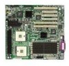
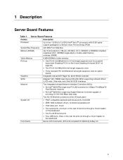
Server Board Features Feature Description Processor Up to two 1.8 GHz to 2.4 GHz Intel® Xeon™ processors with 512K cache support packaged in a 603-... full-length expansion slots • Three standard PCI 33 MHz/32-bit full-length expansion slots for add-in boards Graphics Integrated onboard ATI Rage† XL 32-bit SVGA controller SCSI Adaptec† AIC-7899W dual channel Ultra160 ...the rear I/O and one through a 10-pin header on the baseboard Form Factor Server ATX form factor, ATX 2.03 compliant I/O SSI Entry E-Bay 3.0 9 1 Description Server Board Features Table 1.
Server Board Features Feature Description Processor Up to two 1.8 GHz to 2.4 GHz Intel® Xeon™ processors with 512K cache support packaged in a 603-... full-length expansion slots • Three standard PCI 33 MHz/32-bit full-length expansion slots for add-in boards Graphics Integrated onboard ATI Rage† XL 32-bit SVGA controller SCSI Adaptec† AIC-7899W dual channel Ultra160 ...the rear I/O and one through a 10-pin header on the baseboard Form Factor Server ATX form factor, ATX 2.03 compliant I/O SSI Entry E-Bay 3.0 9 1 Description Server Board Features Table 1.
Product Guide
Page 10
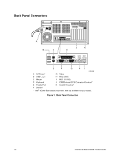
Figure 1. Item may be different on your chassis. Back Panel Connectors 10 Intel Server Board SHG2 Product Guide Back Panel Connectors A B C J K E NIC2 NIC1 (Gbit) (10/100) D F G HI OM14358 A AC Power* G Video B USB 1, 2, 3 H NIC2 (Gbit) C Mouse I NIC1 (10/100) D Keyboard J ICMB/External SCSI Connector Knockout* E Parallel Port K Serial B Knockout* F Serial A * Intel SC5200 Base chassis shown here.
Figure 1. Item may be different on your chassis. Back Panel Connectors 10 Intel Server Board SHG2 Product Guide Back Panel Connectors A B C J K E NIC2 NIC1 (Gbit) (10/100) D F G HI OM14358 A AC Power* G Video B USB 1, 2, 3 H NIC2 (Gbit) C Mouse I NIC1 (10/100) D Keyboard J ICMB/External SCSI Connector Knockout* E Parallel Port K Serial B Knockout* F Serial A * Intel SC5200 Base chassis shown here.
Product Guide
Page 11
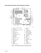
... Component Locations Description 11 Server Board Connector and Component Locations II JJ KK LL HH A GG B FF EE DD CC BB AA Z Y C D E F H J G I K L M N O P Q X W V U T SR A Primary Processor Socket (CPU1) B CPU2 Fan C Secondary Processor ...
... Component Locations Description 11 Server Board Connector and Component Locations II JJ KK LL HH A GG B FF EE DD CC BB AA Z Y C D E F H J G I K L M N O P Q X W V U T SR A Primary Processor Socket (CPU1) B CPU2 Fan C Secondary Processor ...
Product Guide
Page 12
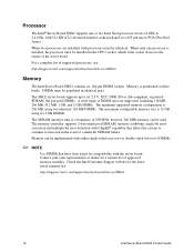
... micro-PGA (Pin-Grid Array). however 266 MHz memory can be used. Check the Intel Customer Support website for a current list of supported processors, see: http://support.intel.com/support/motherboards/server/SHG2 Memory The Intel Server Board SHG2 contains six 184-pin DIMM sockets. The SHG2 server board supports up to six 2.5 V, ECC, DDR 200 or 266-compliant, registered SDRAM 184...
... micro-PGA (Pin-Grid Array). however 266 MHz memory can be used. Check the Intel Customer Support website for a current list of supported processors, see: http://support.intel.com/support/motherboards/server/SHG2 Memory The Intel Server Board SHG2 contains six 184-pin DIMM sockets. The SHG2 server board supports up to six 2.5 V, ECC, DDR 200 or 266-compliant, registered SDRAM 184...
Product Guide
Page 13
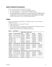
...70, 75, 90, 100 60, 72, 75, 90, 100 43, 60, 70, 72 60, 66, 76, 85 SHG2 2D Mode Video Support 8 bpp 16 bpp 24 bpp 32 bpp Supported Supported Supported Supported Supported Supported Supported Supported Supported Supported Supported... Supported Supported Supported Supported - SHG2 3D Mode Video Support with Z Buffer Enabled Supported Supported Supported Supported Supported Supported Supported Supported Supported Supported Supported Supported Supported Supported - - Add-in Board Connectors The server board has the following add-in board connectors: • Two 184...
...70, 75, 90, 100 60, 72, 75, 90, 100 43, 60, 70, 72 60, 66, 76, 85 SHG2 2D Mode Video Support 8 bpp 16 bpp 24 bpp 32 bpp Supported Supported Supported Supported Supported Supported Supported Supported Supported Supported Supported... Supported Supported Supported Supported - SHG2 3D Mode Video Support with Z Buffer Enabled Supported Supported Supported Supported Supported Supported Supported Supported Supported Supported Supported Supported Supported Supported - - Add-in Board Connectors The server board has the following add-in board connectors: • Two 184...
Product Guide
Page 14
...Capable PCI-X Slot 6 The SHG2 server board supports a modular RAID controller, such as the Intel® RAID Controller SRCMR, on the rear I /O device from the system. The SHG2 Server Board uses an implementation commonly referred to four devices USB Interface The SHG2 Server Board provides three external USB connectors... hiding the host-based I /O panel. An add-in card installed in this feature, see : http://support.intel.com/support/motherboards/server/SHG2 IDE Controller The system includes a dual-channel enhanced IDE 32-bit interface controller for both SCSI channels. The external...
...Capable PCI-X Slot 6 The SHG2 server board supports a modular RAID controller, such as the Intel® RAID Controller SRCMR, on the rear I /O device from the system. The SHG2 Server Board uses an implementation commonly referred to four devices USB Interface The SHG2 Server Board provides three external USB connectors... hiding the host-based I /O panel. An add-in card installed in this feature, see : http://support.intel.com/support/motherboards/server/SHG2 IDE Controller The system includes a dual-channel enhanced IDE 32-bit interface controller for both SCSI channels. The external...
Product Guide
Page 15
...) - As a PCI bus master, the controller can burst data at 100 Mbps • Low-power +3.3 V device • Alert on the Intel 82550PM single-chip Fast Ethernet PCI Bus Controller. The controller has the following: • 32-bit PCI bus master interface (direct drive of bus), ...any 10Base-TX or 100Base-TX switch. • Fast EtherChannel† (FEC) - Network Controllers The server board includes two integrated onboard Network Interface Controllers (NICs). It is an Intel 82544GC Gigabit Ethernet Controller capable of the card you will also slow the 82455GC's interface to 132 MB/s....
...) - As a PCI bus master, the controller can burst data at 100 Mbps • Low-power +3.3 V device • Alert on the Intel 82550PM single-chip Fast Ethernet PCI Bus Controller. The controller has the following: • 32-bit PCI bus master interface (direct drive of bus), ...any 10Base-TX or 100Base-TX switch. • Fast EtherChannel† (FEC) - Network Controllers The server board includes two integrated onboard Network Interface Controllers (NICs). It is an Intel 82544GC Gigabit Ethernet Controller capable of the card you will also slow the 82455GC's interface to 132 MB/s....
Product Guide
Page 16
... adapter. If a Preferred Primary is a simple and efficient way to increase your server or workstation and linked to the same network switch. 16 Intel Server Board SHG2 Product Guide To use ALB, you the ability to set up link recovery to the server adapter in case of four adapters. Adapter teams configured for ALB also provide...
... adapter. If a Preferred Primary is a simple and efficient way to increase your server or workstation and linked to the same network switch. 16 Intel Server Board SHG2 Product Guide To use ALB, you the ability to set up link recovery to the server adapter in case of four adapters. Adapter teams configured for ALB also provide...

Product Guide
Page 17
...state and the processor caches will be programmed to respond to the server board, where BMC firmware and server management software process the signal. If specified through the System Setup Utility (SSU), the server may be dissipating some power, so the power supply fan and ...the system state from the disk and resume normal operation. ACPI The SHG2 supports the Advanced Configuration and Power Interface (ACPI) as defined by locking the keyboard, for a predefined length of the server, Intel® Server Management software monitors the system intrusion switch. Once the inactivity (lockout...
...state and the processor caches will be programmed to respond to the server board, where BMC firmware and server management software process the signal. If specified through the System Setup Utility (SSU), the server may be dissipating some power, so the power supply fan and ...the system state from the disk and resume normal operation. ACPI The SHG2 supports the Advanced Configuration and Power Interface (ACPI) as defined by locking the keyboard, for a predefined length of the server, Intel® Server Management software monitors the system intrusion switch. Once the inactivity (lockout...
Product Guide
Page 18
... Password on Boot is enabled in either the BIOS Setup or SSU. • May enter either password to exit secure mode. 18 Intel Server Board SHG2 Product Guide Using Passwords You can access the system only after a specified time-out period - 1 to 120 minutes. • Set and enable a supervisor password...if you : • Must enter the supervisor password to enter BIOS Setup or the SSU. • Must enter the supervisor password to boot the server if Password on Boot is set either the user password, the supervisor password, or both passwords are enabled, you can set . • Disable ...
... Password on Boot is enabled in either the BIOS Setup or SSU. • May enter either password to exit secure mode. 18 Intel Server Board SHG2 Product Guide Using Passwords You can access the system only after a specified time-out period - 1 to 120 minutes. • Set and enable a supervisor password...if you : • Must enter the supervisor password to enter BIOS Setup or the SSU. • Must enter the supervisor password to boot the server if Password on Boot is set either the user password, the supervisor password, or both passwords are enabled, you can set . • Disable ...
Product Guide
Page 20
...then you cannot access Setup, change the Clear Password jumper (see Chapter 7). During POST, before accepting any keyboard or mouse input. 20 Intel Server Board SHG2 Product Guide If secure mode is enabled (a user password is set a supervisor password and enable it through Setup. To resume activity: Enter ...The sequence that keyboard and mouse input are enabled through Setup. If no keyboard or mouse action occurs for a password before the server fully boots. To clear the password if you specify in the Security Subsystem Group. If secure mode is enabled and the "Secure...
...then you cannot access Setup, change the Clear Password jumper (see Chapter 7). During POST, before accepting any keyboard or mouse input. 20 Intel Server Board SHG2 Product Guide If secure mode is enabled (a user password is set a supervisor password and enable it through Setup. To resume activity: Enter ...The sequence that keyboard and mouse input are enabled through Setup. If no keyboard or mouse action occurs for a password before the server fully boots. To clear the password if you specify in the Security Subsystem Group. If secure mode is enabled and the "Secure...
Product Guide
Page 21
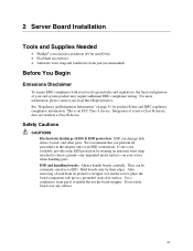
... and EMC regulatory compliance information. Do not slide board over any unpainted metal surfaceon your server when handling parts. If one is an FCC Class A device. ESD and handling boards: Always handle boards carefully. 2 Server Board Installation Tools and Supplies Needed • Phillips†... chapter only at an ESD workstation. Integration of your local Intel Representative. We recommend that you perform all procedures in a Class B device. Use a conductive foam pad if available but not the board wrapper. See "Regulatory and Integration Information" on a grounded,...
... and EMC regulatory compliance information. Do not slide board over any unpainted metal surfaceon your server when handling parts. If one is an FCC Class A device. ESD and handling boards: Always handle boards carefully. 2 Server Board Installation Tools and Supplies Needed • Phillips†... chapter only at an ESD workstation. Integration of your local Intel Representative. We recommend that you perform all procedures in a Class B device. Use a conductive foam pad if available but not the board wrapper. See "Regulatory and Integration Information" on a grounded,...
Product Guide
Page 22
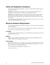
... more information on supported processors and qualified memory and chassis components, see: http://support.intel.com/support/motherboards/server/SHG2 Processor A minimum of 450 W with 1.2 A +5 V standby current (in an easy-to-see : http://www.ssiforum.org 22 Intel Server Board SHG2 Product Guide For more information on the SSI EPS 12 V specification, see location, preferably oriented similarly to...
... more information on supported processors and qualified memory and chassis components, see: http://support.intel.com/support/motherboards/server/SHG2 Processor A minimum of 450 W with 1.2 A +5 V standby current (in an easy-to-see : http://www.ssiforum.org 22 Intel Server Board SHG2 Product Guide For more information on the SSI EPS 12 V specification, see location, preferably oriented similarly to...
Product Guide
Page 23
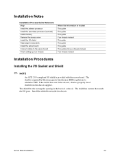
...obtain a properly sized shield from inside the chassis. The shield is required by Electromagnetic Interference (EMI) regulations to the server board Finish setting up your chassis Where the information is located This guide This guide This guide Your chassis manual This guide ...chassis manual Installation Procedures Installing the I/O Gasket and Shield ✏ NOTE An ATX 2.03-compliant I/O shield is provided with the server board. The shield has cutouts that match the I/O ports. Installation Notes Installation Process Quick Reference Step Install the primary processor Install the ...
...obtain a properly sized shield from inside the chassis. The shield is required by Electromagnetic Interference (EMI) regulations to the server board Finish setting up your chassis Where the information is located This guide This guide This guide Your chassis manual This guide ...chassis manual Installation Procedures Installing the I/O Gasket and Shield ✏ NOTE An ATX 2.03-compliant I/O shield is provided with the server board. The shield has cutouts that match the I/O ports. Installation Notes Installation Process Quick Reference Step Install the primary processor Install the ...
Product Guide
Page 24
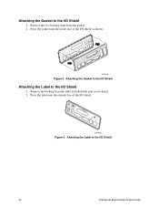
Remove the two backing strips from the label included with your server board. 2. OM14359 Figure 3. Remove the backing from the gasket. 2. Press the label onto the outside face of the I/O shield as shown. Press the gasket onto the inside face of the I /O Shield 24 Intel Server Board SHG2 Product Guide Attaching the Gasket to the I/O Shield Attaching the Label to the I /O shield. Attaching the Label to the I /O Shield 1. USB 1 2 3 KMYOBUDSE PARALLEL (GNbIiCt)2 (10N/1I0C01) OM14360 Figure 4. Attaching the Gasket to the I /O Shield 1.
Remove the two backing strips from the label included with your server board. 2. OM14359 Figure 3. Remove the backing from the gasket. 2. Press the label onto the outside face of the I/O shield as shown. Press the gasket onto the inside face of the I /O Shield 24 Intel Server Board SHG2 Product Guide Attaching the Gasket to the I/O Shield Attaching the Label to the I /O shield. Attaching the Label to the I /O Shield 1. USB 1 2 3 KMYOBUDSE PARALLEL (GNbIiCt)2 (10N/1I0C01) OM14360 Figure 4. Attaching the Gasket to the I /O Shield 1.


