User Guide
Page 2
... to determine the amount of airflow required for cooling. Copyright © 2004, Intel Corporation. Intel may occur. Intel server boards contain a number of their specific application and environmental conditions. Intel, Intel Pentium, and Intel Xeon are trademarks or registered trademarks of Intel Corporation or its subsidiaries in Intel's Terms and Conditions of any time, without notice. Disclaimer Information in this...
... to determine the amount of airflow required for cooling. Copyright © 2004, Intel Corporation. Intel may occur. Intel server boards contain a number of their specific application and environmental conditions. Intel, Intel Pentium, and Intel Xeon are trademarks or registered trademarks of Intel Corporation or its subsidiaries in Intel's Terms and Conditions of any time, without notice. Disclaimer Information in this...

User Guide
Page 3
... step-bystep instructions and diagrams for Intel products, see http://support.intel.com/support/motherboards/server/SE7520JR2/compat.htm. Intel® Server Board SE7520JR2 User Guide iii For the latest version of the following Intel® Server Chassis: ƒ Intel® Server Chassis SR1400 ƒ Intel® Server Chassis SR2400 You may need , troubleshooting information, and instructions on the Intel Server Board SE7520JR2. Information about which accessories, memory, processors...
... step-bystep instructions and diagrams for Intel products, see http://support.intel.com/support/motherboards/server/SE7520JR2/compat.htm. Intel® Server Board SE7520JR2 User Guide iii For the latest version of the following Intel® Server Chassis: ƒ Intel® Server Chassis SR1400 ƒ Intel® Server Chassis SR2400 You may need , troubleshooting information, and instructions on the Intel Server Board SE7520JR2. Information about which accessories, memory, processors...

User Guide
Page 4
...Document or Software Intel® Server Board SE7520JR2 Technical Product Specification Intel® Server Board SE7520JR2 Quick Start User's Guide in the search field at http://support.intel.com/support/motherboards/server/SE7520JR2 Accessories or other Intel server products Spares and Configuration Guide Hardware (peripheral boards, adapter cards... falls within the allowed power budget For software to manage your server board iv These files are available at http://support.intel.com/support/motherboards/server/SE7520JR2/ Unless otherwise indicated in the table below, once on this Web...
...Document or Software Intel® Server Board SE7520JR2 Technical Product Specification Intel® Server Board SE7520JR2 Quick Start User's Guide in the search field at http://support.intel.com/support/motherboards/server/SE7520JR2 Accessories or other Intel server products Spares and Configuration Guide Hardware (peripheral boards, adapter cards... falls within the allowed power budget For software to manage your server board iv These files are available at http://support.intel.com/support/motherboards/server/SE7520JR2/ Unless otherwise indicated in the table below, once on this Web...
User Guide
Page 5
...) and operating at the same (or higher) speed as Information Technology Equipment (ITE), which the product is an FCC Class A device. This is sold. Intel® Server Board SE7520JR2 User Guide v The suitability of it into a Class B chassis does not result in this guide to the safety instructions. Use only the described, regulated components...
...) and operating at the same (or higher) speed as Information Technology Equipment (ITE), which the product is an FCC Class A device. This is sold. Intel® Server Board SE7520JR2 User Guide v The suitability of it into a Class B chassis does not result in this guide to the safety instructions. Use only the described, regulated components...
User Guide
Page 7
...der Ressourcen-CD oder unter http://support.intel.com/support/motherboards/server/sb/cs-010770.htm. Ziehen Sie den Stromanschlußstecker Ihres Systems aus der Steckdose. 4. Arbeiten an Platinen und Gehäuse ein. Intel® Server Board SE7520JR2 User Guide vii Turn off all peripheral ...nnen einige Platinen und Gehäuseteile scharfe Spitzen und Kanten aufweisen. See also Intel Server Boards and Server Chassis Safety Information on the Resource CD and/or at http://support.intel.com/support/motherboards/server/sb/cs-010770.htm. Turn off the system by wearing an antistatic wrist ...
...der Ressourcen-CD oder unter http://support.intel.com/support/motherboards/server/sb/cs-010770.htm. Ziehen Sie den Stromanschlußstecker Ihres Systems aus der Steckdose. 4. Arbeiten an Platinen und Gehäuse ein. Intel® Server Board SE7520JR2 User Guide vii Turn off all peripheral ...nnen einige Platinen und Gehäuseteile scharfe Spitzen und Kanten aufweisen. See also Intel Server Boards and Server Chassis Safety Information on the Resource CD and/or at http://support.intel.com/support/motherboards/server/sb/cs-010770.htm. Turn off the system by wearing an antistatic wrist ...
User Guide
Page 11
Contents Contents 1 Server Board Features 15 Connector and Header Locations 18 Configuration Jumpers ...19 Back Panel Connectors...20 Hardware Requirements ...21 Processor ...21 Memory ...21 Optional Hardware ...24 Hard Disk Drives ...24 Intel® Management Module 24 Intel® Local Control Panel 24 2 Hardware Installations and Upgrades 25 Before You Begin ...25 Tools and ... Operation of Key System Lights 41 Confirming Loading of the Operating System 41 Specific Problems and Corrective Actions 42 Power Light Does Not Light 42 Intel® Server Board SE7520JR2 User Guide xi
Contents Contents 1 Server Board Features 15 Connector and Header Locations 18 Configuration Jumpers ...19 Back Panel Connectors...20 Hardware Requirements ...21 Processor ...21 Memory ...21 Optional Hardware ...24 Hard Disk Drives ...24 Intel® Management Module 24 Intel® Local Control Panel 24 2 Hardware Installations and Upgrades 25 Before You Begin ...25 Tools and ... Operation of Key System Lights 41 Confirming Loading of the Operating System 41 Specific Problems and Corrective Actions 42 Power Light Does Not Light 42 Intel® Server Board SE7520JR2 User Guide xi
User Guide
Page 13
...DIMM Module Memory Capacity Support 22 Keyboard Commands 35 POST Error Beep Codes 49 Error Beep Codes Provided by Intel® Management Modules 49 Product Certification Markings 52 Intel® Server Board SE7520JR2 User Guide xiii Server Board Connector and Component Locations 18 Figure 3. Opening Socket Lever 28 Figure 7. Closing Socket Lever 29 Figure 9.... the Backup Battery 33 Figure 12. Table 2. Contents Figures Figure 1. Table 4. Password Recovery Jumper 37 Figure 13. Installing Memory...26 Figure 6. Intel® Server Board SE7520JR2 15 Figure 2.
...DIMM Module Memory Capacity Support 22 Keyboard Commands 35 POST Error Beep Codes 49 Error Beep Codes Provided by Intel® Management Modules 49 Product Certification Markings 52 Intel® Server Board SE7520JR2 User Guide xiii Server Board Connector and Component Locations 18 Figure 3. Opening Socket Lever 28 Figure 7. Closing Socket Lever 29 Figure 9.... the Backup Battery 33 Figure 12. Table 2. Contents Figures Figure 1. Table 4. Password Recovery Jumper 37 Figure 13. Installing Memory...26 Figure 6. Intel® Server Board SE7520JR2 15 Figure 2.

User Guide
Page 15
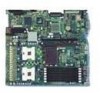
... follows: ƒ SE7520JR2SCSID2: On-board SCSI, on-board SATA (RAID), and DDR-2 400MHz ƒ SE7520JR2SCSID1: On-board SCSI, on the server board. Intel® Server Board SE7520JR2 Intel® Server Board SE7520JR2 User Guide 15 This document applies to each version. The primary differences are indicated where applicable. 1 Server Board Features This chapter briefly describes the main features of the Server Board SE7520JR2 are available. This chapter provides...
... follows: ƒ SE7520JR2SCSID2: On-board SCSI, on-board SATA (RAID), and DDR-2 400MHz ƒ SE7520JR2SCSID1: On-board SCSI, on the server board. Intel® Server Board SE7520JR2 Intel® Server Board SE7520JR2 User Guide 15 This document applies to each version. The primary differences are indicated where applicable. 1 Server Board Features This chapter briefly describes the main features of the Server Board SE7520JR2 are available. This chapter provides...

User Guide
Page 16
...-profile PCI-X 66/100MHz add-in cards. One full-height riser slot, utilizing Intel® Adaptive Slot technology. Video On-board ATI* RAGE XL video controller with an 800 MT/s MHz front side bus and frequencies starting at 2.8 GHz. Server Board Features Feature Description Processors Memory Chipset Support for 10/100/1000 Mb connections...
...-profile PCI-X 66/100MHz add-in cards. One full-height riser slot, utilizing Intel® Adaptive Slot technology. Video On-board ATI* RAGE XL video controller with an 800 MT/s MHz front side bus and frequencies starting at 2.8 GHz. Server Board Features Feature Description Processors Memory Chipset Support for 10/100/1000 Mb connections...

User Guide
Page 17
... primary channel routes through the 100-pin flex cable. One 20-pin fan connector providing fan speed control and monitoring for system fans in a common server configuration is not supported. Server Board Features Table 1. Support for Intel® Server Management 8.x Intel® Light-Guided Diagnostics on all field replaceable units (FRUs) Intel® Server Board SE7520JR2 User Guide 17
... primary channel routes through the 100-pin flex cable. One 20-pin fan connector providing fan speed control and monitoring for system fans in a common server configuration is not supported. Server Board Features Table 1. Support for Intel® Server Management 8.x Intel® Light-Guided Diagnostics on all field replaceable units (FRUs) Intel® Server Board SE7520JR2 User Guide 17
User Guide
Page 19
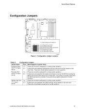
... jumpered for normal operation. This jumper is typically used when the BIOS has become corrupted. These pins should not be cleared on the next reset. Intel® Server Board SE7520JR2 User Guide 19 Configuration Jumper Location Table 2. Password Clear 1-2 These pins should be jumpered for normal system operation. (line "A" in figure 2-3 above ) BIOS code...
... jumpered for normal operation. This jumper is typically used when the BIOS has become corrupted. These pins should not be cleared on the next reset. Intel® Server Board SE7520JR2 User Guide 19 Configuration Jumper Location Table 2. Password Clear 1-2 These pins should be jumpered for normal system operation. (line "A" in figure 2-3 above ) BIOS code...
User Guide
Page 20
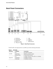
... Solid Green Description No network connection Network connection in place Transmit/receive activity 10 Mbps connection (if left of each NIC provide the following information. Server Board Features Back Panel Connectors A B C D E F GH I TP00762 A PS/2 Mouse F Video B PS/2 Keyboard G USB port 1 C Serial Port B H USB port 2 D NIC port 1 (1 Gb) I SCSI channel B E NIC port 2 (1 Gb...
... Solid Green Description No network connection Network connection in place Transmit/receive activity 10 Mbps connection (if left of each NIC provide the following information. Server Board Features Back Panel Connectors A B C D E F GH I TP00762 A PS/2 Mouse F Video B PS/2 Keyboard G USB port 1 C Serial Port B H USB port 2 D NIC port 1 (1 Gb) I SCSI channel B E NIC port 2 (1 Gb...
User Guide
Page 21
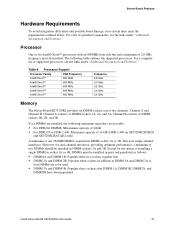
...; Xeon™ 800 MHz Frequency 2.8 GHz 3.0 GHz 3.2 GHz 3.4 GHz 3.6 GHz Memory The Server Board SE7520JR2 provides six DIMM sockets across two channels, Channel A and Channel B. This uses single-channel interleave. Intel® Server Board SE7520JR2 User Guide 21 The following maximum capacitites are possible: ƒ For DDR266 DIMMS: Maxixmum capacity of 24GB ƒ For DDR333 or DDR...
...; Xeon™ 800 MHz Frequency 2.8 GHz 3.0 GHz 3.2 GHz 3.4 GHz 3.6 GHz Memory The Server Board SE7520JR2 provides six DIMM sockets across two channels, Channel A and Channel B. This uses single-channel interleave. Intel® Server Board SE7520JR2 User Guide 21 The following maximum capacitites are possible: ƒ For DDR266 DIMMS: Maxixmum capacity of 24GB ƒ For DDR333 or DDR...

User Guide
Page 22
... be considered. In a mirrored system, the maximum usable memory is supported. Memory Sparing and Mirroring The Intel® E7520 chipset includes hardware that supports memory mirroring and memory on boards that up to the Intel® Server Board SE7520JR2 Technical Product Specification for additional information regarding the memory sub-system. For a complete list of four loads...
... be considered. In a mirrored system, the maximum usable memory is supported. Memory Sparing and Mirroring The Intel® E7520 chipset includes hardware that supports memory mirroring and memory on boards that up to the Intel® Server Board SE7520JR2 Technical Product Specification for additional information regarding the memory sub-system. For a complete list of four loads...
User Guide
Page 23
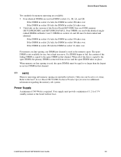
... Your supply must be active at a time. When memory on the versions of 5 V standby current or the board will not boot. Intel® Server Board SE7520JR2 User Guide 23 Server Board Features Two methods for memory mirroring are available: ƒ Four identical DIMMs are used in that channel. ✏.... If the DIMM in socket 1B fails, the DIMM in socket 2A takes over . If a DIMM begins to the Intel® Server Board SE7520JR2 Technical Product Specification for additional information regarding the memory sub-system. Refer to fail, the content of the failing DIMM is used...
... Your supply must be active at a time. When memory on the versions of 5 V standby current or the board will not boot. Intel® Server Board SE7520JR2 User Guide 23 Server Board Features Two methods for memory mirroring are available: ƒ Four identical DIMMs are used in that channel. ✏.... If the DIMM in socket 1B fails, the DIMM in socket 2A takes over . If a DIMM begins to the Intel® Server Board SE7520JR2 Technical Product Specification for additional information regarding the memory sub-system. Refer to fail, the content of the failing DIMM is used...

User Guide
Page 24
.../100 drives. See the documentation included with the management module. Advanced Edition: includes a hardware mezzanine card, 10/100 Mb NIC mezzanine card, and cables. Server Board Features Optional Hardware Hard Disk Drives The Server Board SE7520JR2 supports different hard disk drive options, depending on installing either Intel® Management Module, Professional Edition or Advance Edition. 24
.../100 drives. See the documentation included with the management module. Advanced Edition: includes a hardware mezzanine card, 10/100 Mb NIC mezzanine card, and cables. Server Board Features Optional Hardware Hard Disk Drives The Server Board SE7520JR2 supports different hard disk drive options, depending on installing either Intel® Management Module, Professional Edition or Advance Edition. 24
User Guide
Page 25
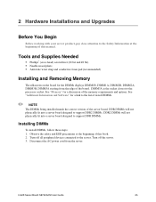
... power cord from the edge of the board. DIMM3A is the socket closest to support DDR DIMMs. Installing DIMMs To install DIMMs, follow these steps: 1. Turn off all peripheral devices connected to the server. Intel® Server Board SE7520JR2 User Guide 25 2 Hardware Installations and ...Upgrades Before You Begin Before working with your server product, pay close attention to the Safety Information at the beginning of this...
... power cord from the edge of the board. DIMM3A is the socket closest to support DDR DIMMs. Installing DIMMs To install DIMMs, follow these steps: 1. Turn off all peripheral devices connected to the server. Intel® Server Board SE7520JR2 User Guide 25 2 Hardware Installations and ...Upgrades Before You Begin Before working with your server product, pay close attention to the Safety Information at the beginning of this...
User Guide
Page 27
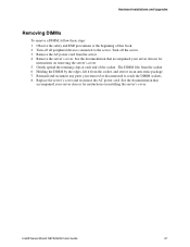
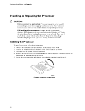
...the server. 3. Remove the server's cover. Intel® Server Board SE7520JR2 User Guide 27 Observe the safety and ESD precautions at each end of this book. 2. Gently spread the retaining clips at the beginning of the socket. The DIMM lifts from the server. 4. Replace the server's ... cord from the socket. 6. See the documentation that accompanied your server chassis for instructions on installing the server's cover. See the documentation that accompanied your server chassis for instructions on removing the server's cover. 5. Holding the DIMM by the edges, lift it ...
...the server. 3. Remove the server's cover. Intel® Server Board SE7520JR2 User Guide 27 Observe the safety and ESD precautions at each end of this book. 2. Gently spread the retaining clips at the beginning of the socket. The DIMM lifts from the server. 4. Replace the server's ... cord from the socket. 6. See the documentation that accompanied your server chassis for instructions on installing the server's cover. See the documentation that accompanied your server chassis for instructions on removing the server's cover. 5. Holding the DIMM by the edges, lift it ...
User Guide
Page 28
... the processor by doing the following: (1) Touch the metal chassis before touching the processor or server board. See the documentation that is inappropriate for your server. Keep part of compatible processor(s). Opening Socket Lever 28 ESD and handling processors: Reduce the ... or Replacing the Processor CAUTIONS Processor must be appropriate: You may damage the server board if you install a processor that accompanied your server chassis for instructions on removing the server's cover 5. Observe the safety and ESD precautions at the beginning of electrostatic discharge...
... the processor by doing the following: (1) Touch the metal chassis before touching the processor or server board. See the documentation that is inappropriate for your server. Keep part of compatible processor(s). Opening Socket Lever 28 ESD and handling processors: Reduce the ... or Replacing the Processor CAUTIONS Processor must be appropriate: You may damage the server board if you install a processor that accompanied your server chassis for instructions on removing the server's cover 5. Observe the safety and ESD precautions at the beginning of electrostatic discharge...
User Guide
Page 29
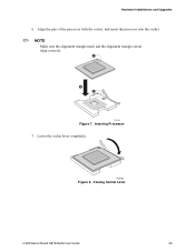
A B A TP00764 Figure 7. TP00765 Figure 8. Inserting Processor 7. Lower the socket lever completely. Closing Socket Lever Intel® Server Board SE7520JR2 User Guide 29 Align the pins of the processor with the socket, and insert the processor into the socket. ✏ NOTE Make sure the alignment triangle mark and the alignment triangle cutout align correctly. Hardware Installations and Upgrades 6.
A B A TP00764 Figure 7. TP00765 Figure 8. Inserting Processor 7. Lower the socket lever completely. Closing Socket Lever Intel® Server Board SE7520JR2 User Guide 29 Align the pins of the processor with the socket, and insert the processor into the socket. ✏ NOTE Make sure the alignment triangle mark and the alignment triangle cutout align correctly. Hardware Installations and Upgrades 6.


