User Guide
Page 11
... (CE Declaration of Conformity 48 VCCI (Japan) ...48 BSMI (Taiwan)...49 RRL (Korea) ...49 CNCA (CCC-China)...49 Intel® Server Issue Report Form 53 xii Intel® Server Board SE7520AF2 User Guide Contents CD-ROM Drive or DVD-ROM Drive Activity Light Does Not Light 39 Cannot Connect to a Server... are not Recognized under Device Manager (Windows* Operating System)...41 Hard Drive(s) are not Recognized 41 Bootable CD-ROM Is Not Detected 41 LED Information ...42 BIOS POST Beep Codes 43 Boot Block Error Beep Codes 43 POST Error Beep Codes 44 BIOS Recovery Beep Codes 44 Regulatory...
... (CE Declaration of Conformity 48 VCCI (Japan) ...48 BSMI (Taiwan)...49 RRL (Korea) ...49 CNCA (CCC-China)...49 Intel® Server Issue Report Form 53 xii Intel® Server Board SE7520AF2 User Guide Contents CD-ROM Drive or DVD-ROM Drive Activity Light Does Not Light 39 Cannot Connect to a Server... are not Recognized under Device Manager (Windows* Operating System)...41 Hard Drive(s) are not Recognized 41 Bootable CD-ROM Is Not Detected 41 LED Information ...42 BIOS POST Beep Codes 43 Boot Block Error Beep Codes 43 POST Error Beep Codes 44 BIOS Recovery Beep Codes 44 Regulatory...

User Guide
Page 12
...Resetting the System 34 Table 6. Contents Figures Figure 1. Installing Memory...12 Figure 9. Clearing the CMOS Jumper 27 Tables Table 1. Intel® Server Board SE7520AF2 1 Figure 2. Six DIMM Memory Mirroring 8 Figure 7. Inserting Processor 14 Figure 11. Boot Block Error Beep Codes 43 Table ...8. Troubleshooting BIOS Beep Codes 44 Intel® Server Board SE7520AF2 User Guide xiii Server Board Connector and Header Locations 4 Figure 3. Eight DIMM Memory Mirroring 8 Figure 8. Closing Socket Lever 15 Figure 12. PCI Hot-plug LEDs at Rear of Chassis 18 Figure 15....
...Resetting the System 34 Table 6. Contents Figures Figure 1. Installing Memory...12 Figure 9. Clearing the CMOS Jumper 27 Tables Table 1. Intel® Server Board SE7520AF2 1 Figure 2. Six DIMM Memory Mirroring 8 Figure 7. Inserting Processor 14 Figure 11. Boot Block Error Beep Codes 43 Table ...8. Troubleshooting BIOS Beep Codes 44 Intel® Server Board SE7520AF2 User Guide xiii Server Board Connector and Header Locations 4 Figure 3. Eight DIMM Memory Mirroring 8 Figure 8. Closing Socket Lever 15 Figure 12. PCI Hot-plug LEDs at Rear of Chassis 18 Figure 15....

User Guide
Page 18
...; Server Chassis SC5300 PCI Hot Plug Upgrade kit are installed, the LEDs in the I/O port area provide attention information for PCI slots 1, 3, 4, and 5. 6 Intel® Server Board SE7520AF2 User Guide Back Panel Connectors E F TP00663 The NIC LEDs at the right and left LED is in place Transmit/receive activity 10 Mbps connection (if left of...
...; Server Chassis SC5300 PCI Hot Plug Upgrade kit are installed, the LEDs in the I/O port area provide attention information for PCI slots 1, 3, 4, and 5. 6 Intel® Server Board SE7520AF2 User Guide Back Panel Connectors E F TP00663 The NIC LEDs at the right and left LED is in place Transmit/receive activity 10 Mbps connection (if left of...

User Guide
Page 29
... be hot plugged (slots 1, 3, 4, and 5) and it is to remove the shield. The power LED next to a slot for slots that holds the PCI bracket shield to the rear of the chassis to...In a hot-plug system, stand the hot-plug curtains on the top edge of your server chassis documentation for LED placement inside of the card to be installed and insert the card between them to add or remove a card ... is green for each side of the server chassis to ensure it is fully seated. 18 Intel® Server Board SE7520AF2 User Guide If removing a card from or into the PCI slot on the blue or green...
... be hot plugged (slots 1, 3, 4, and 5) and it is to remove the shield. The power LED next to a slot for slots that holds the PCI bracket shield to the rear of the chassis to...In a hot-plug system, stand the hot-plug curtains on the top edge of your server chassis documentation for LED placement inside of the card to be installed and insert the card between them to add or remove a card ... is green for each side of the server chassis to ensure it is fully seated. 18 Intel® Server Board SE7520AF2 User Guide If removing a card from or into the PCI slot on the blue or green...

User Guide
Page 30
...card retainer. A A E C B D TP00860 Figure 15. See your server chassis documentation for instructions. Hot plug systems only: Watch for the power LED next to remove the PCI add-in Figure 15. If you just inserted. 14. See letter A and letter E in card retainer to turn on adding... plug systems only: Use the hot-plug interface utility available through your server chassis documentation for easy access. 13. Intel® Server Board SE7520AF2 User Guide 19 The amber LED should be off, to secure the PCI card into the slot. Installing a PCI Card 12. Install the chassis...
...card retainer. A A E C B D TP00860 Figure 15. See your server chassis documentation for instructions. Hot plug systems only: Watch for the power LED next to remove the PCI add-in Figure 15. If you just inserted. 14. See letter A and letter E in card retainer to turn on adding... plug systems only: Use the hot-plug interface utility available through your server chassis documentation for easy access. 13. Intel® Server Board SE7520AF2 User Guide 19 The amber LED should be off, to secure the PCI card into the slot. Installing a PCI Card 12. Install the chassis...

User Guide
Page 39
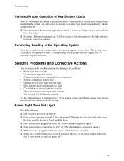
...the system power cord properly connected to at least two thirds of their maximum ranges (see "Power Light Does Not Light." 28 Intel® Server Board SE7520AF2 User Guide Turn off the system and any external peripheral devices. Make sure your video display monitor). 4. Turn on the video... to the system and plugged into a properly grounded AC outlet. 3. Disconnect each device from a CD-ROM disk. 6. If the power LED does not light, see the documentation supplied with them. Troubleshooting ‰ Are all external peripheral devices. If the operating system normally loads from...
...the system power cord properly connected to at least two thirds of their maximum ranges (see "Power Light Does Not Light." 28 Intel® Server Board SE7520AF2 User Guide Turn off the system and any external peripheral devices. Make sure your video display monitor). 4. Turn on the video... to the system and plugged into a properly grounded AC outlet. 3. Disconnect each device from a CD-ROM disk. 6. If the power LED does not light, see the documentation supplied with them. Troubleshooting ‰ Are all external peripheral devices. If the operating system normally loads from...
User Guide
Page 40
...prompt appears on briefly. If the operating system prompt does not appear, see "Diskette Drive Activity Light Does Not Light." ‰ If system LEDs are problems with application software. ƒ The bootable CD-ROM is not detected. Power Light Does Not Light Check the following : ‰...ƒ Hard disk drive activity light does not light. ƒ CD-ROM drive activity light does not light. ƒ There are illuminated, see "LED Information" for these specific problems: ƒ Power light does not light. ƒ No characters appear on screen. ƒ Characters on briefly? The ...
...prompt appears on briefly. If the operating system prompt does not appear, see "Diskette Drive Activity Light Does Not Light." ‰ If system LEDs are problems with application software. ƒ The bootable CD-ROM is not detected. Power Light Does Not Light Check the following : ‰...ƒ Hard disk drive activity light does not light. ƒ CD-ROM drive activity light does not light. ƒ There are illuminated, see "LED Information" for these specific problems: ƒ Power light does not light. ƒ No characters appear on screen. ƒ Characters on briefly? The ...
User Guide
Page 42
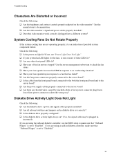
..." is an indication of the fan motors stopped? If you are using an add-in response to an overheating situation? ‰ Have your system has LED lights for the fans, is set to check the fan status. ‰ Have your fans speeds increased in RPM in diskette controller, make sure that... "Onboard Floppy" is one or more of these LEDs lit? ‰ Are any other front panel LEDs lit? ‰ Have any shorted wires caused by pinched-cables or have power connector plugs been forced into a different system? See...
..." is an indication of the fan motors stopped? If you are using an add-in response to an overheating situation? ‰ Have your system has LED lights for the fans, is set to check the fan status. ‰ Have your fans speeds increased in RPM in diskette controller, make sure that... "Onboard Floppy" is one or more of these LEDs lit? ‰ Are any other front panel LEDs lit? ‰ Have any shorted wires caused by pinched-cables or have power connector plugs been forced into a different system? See...

User Guide
Page 43
...; Make sure the correct networking software is securely attached. ‰ Make sure you will need a crossover cable. ‰ Check the network controller LEDs next to the NIC connectors. Cannot Connect to the correct connector at the system back panel. ‰ Try a different network cable. ‰ ... the port from the onboard network controller. ‰ Make sure your NET.CFG file. Delete and then reinstall the drivers. 32 Intel® Server Board SE7520AF2 User Guide See "Additional Information and Software" for a link to the current version. ‰ Make sure the other PCI drivers....
...; Make sure the correct networking software is securely attached. ‰ Make sure you will need a crossover cable. ‰ Check the network controller LEDs next to the NIC connectors. Cannot Connect to the correct connector at the system back panel. ‰ Try a different network cable. ‰ ... the port from the onboard network controller. ‰ Make sure your NET.CFG file. Delete and then reinstall the drivers. 32 Intel® Server Board SE7520AF2 User Guide See "Additional Information and Software" for a link to the current version. ‰ Make sure the other PCI drivers....

User Guide
Page 46
...; Blinking = Slot is transitioning between on or S0) ƒ Slow Blink = Low power state (S1 - Troubleshooting LED Information The Intel® Server Board SE7520AF2 includes LEDs that can aid in server identification from the back panel System fault Visible fault warning Location Front panel and board rear left...memory module POST code 1-4 (LSB, bit1, bit2, MSB) Fan Pack Fault CPU 1 & 2 Fan Fault CPU 1 & 2 Fault 5v Standby Power LED Display boot 80 POST code Warn on fan failure Identify fan failure Identify processor failure Identify 5v standby power on state Identify the power state...
...; Blinking = Slot is transitioning between on or S0) ƒ Slow Blink = Low power state (S1 - Troubleshooting LED Information The Intel® Server Board SE7520AF2 includes LEDs that can aid in server identification from the back panel System fault Visible fault warning Location Front panel and board rear left...memory module POST code 1-4 (LSB, bit1, bit2, MSB) Fan Pack Fault CPU 1 & 2 Fan Fault CPU 1 & 2 Fault 5v Standby Power LED Display boot 80 POST code Warn on fan failure Identify fan failure Identify processor failure Identify 5v standby power on state Identify the power state...

User Guide
Page 47
... (file layout does not match image present in flash device) 1 long beep Insert diskette with AMIBOOT.001 File for Multi-Disk Recovery 36 Intel® Server Board SE7520AF2 User Guide LED Name Hot-plug PCI Attention (hot plug system PCI only) Function Indicates a fault condition has occurred Location Inside the system, at the...
... (file layout does not match image present in flash device) 1 long beep Insert diskette with AMIBOOT.001 File for Multi-Disk Recovery 36 Intel® Server Board SE7520AF2 User Guide LED Name Hot-plug PCI Attention (hot plug system PCI only) Function Indicates a fault condition has occurred Location Inside the system, at the...


