Product Specification
Page 4
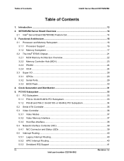
... 3.1.1 Processor Support 16 3.1.2 Memory Subsystem 17 3.2 The Intel® E7505 Chipset 21 3.2.1 MCH Memory Architecture Overview 22 3.2.2 Memory Controller Hub (MCH 23 3.2.3 P64H2 ...24 3.2.4 ICH4 ...24 3.3 Super I /O Subsystem ...33 5.1 PCI Subsystem ...33 5.1.1 P32-A: 32-bit/33-MHz PCI Subsystem 33 5.1.2 P64-B and P64-C: 64-bit/100- Introduction ...13 2. Table of Contents Intel® Server Board SE7505VB2 Table...
... 3.1.1 Processor Support 16 3.1.2 Memory Subsystem 17 3.2 The Intel® E7505 Chipset 21 3.2.1 MCH Memory Architecture Overview 22 3.2.2 Memory Controller Hub (MCH 23 3.2.3 P64H2 ...24 3.2.4 ICH4 ...24 3.3 Super I /O Subsystem ...33 5.1 PCI Subsystem ...33 5.1.1 P32-A: 32-bit/33-MHz PCI Subsystem 33 5.1.2 P64-B and P64-C: 64-bit/100- Introduction ...13 2. Table of Contents Intel® Server Board SE7505VB2 Table...
Product Specification
Page 9
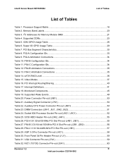
...100-MHz PCI-X Slot Pin-out (J2B1, J2B2 56 Table 28. Front Panel 34-Pin Header Pin-out (J1J1 59 Table 31. Processor Support Matrix 16 Table 2. ICH4 GPIO Usage Table 26 Table 6. PCI Bus Segment Characteristics 33 Table 8. Power Connector Pin-out (J9B1 50 Table...55 Table 27. I2C Addresses for Memory Module SMB 21 Table 4. Supported DDRs...23 Table 5. P64-B Configuration IDs 34 Table 11. Super I/O GPIO Usage Table 29 Table 7. Supported Wake Events 49 Table 20. Auxiliary Signal Connector (J7K1 50 Table 22. Intel® Server Board SE7505VB2 List of Tables List of Tables...
...100-MHz PCI-X Slot Pin-out (J2B1, J2B2 56 Table 28. Front Panel 34-Pin Header Pin-out (J1J1 59 Table 31. Processor Support Matrix 16 Table 2. ICH4 GPIO Usage Table 26 Table 6. PCI Bus Segment Characteristics 33 Table 8. Power Connector Pin-out (J9B1 50 Table...55 Table 27. I2C Addresses for Memory Module SMB 21 Table 4. Supported DDRs...23 Table 5. P64-B Configuration IDs 34 Table 11. Super I/O GPIO Usage Table 29 Table 7. Supported Wake Events 49 Table 20. Auxiliary Signal Connector (J7K1 50 Table 22. Intel® Server Board SE7505VB2 List of Tables List of Tables...
Product Specification
Page 14
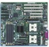
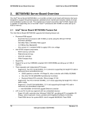
... DDR266 compliant ECC DDR DIMMs providing up to supply CPU core voltage Intel E7505 chipset components - SE7505VB2 Server Board Overview Intel® Server Board SE7505VB2 2. Dual Intel Xeon processors with 8 MB of memory. 2.1 Intel® Server Board SE7505VB2 Feature Set The Intel Server Board SE7505VB2 supports the following feature set: Processor/FSB support - P64H2 64-bit I/O Hub - FWH Firmware Hub Glue4-PAL...
... DDR266 compliant ECC DDR DIMMs providing up to supply CPU core voltage Intel E7505 chipset components - SE7505VB2 Server Board Overview Intel® Server Board SE7505VB2 2. Dual Intel Xeon processors with 8 MB of memory. 2.1 Intel® Server Board SE7505VB2 Feature Set The Intel Server Board SE7505VB2 supports the following feature set: Processor/FSB support - P64H2 64-bit I/O Hub - FWH Firmware Hub Glue4-PAL...
Product Specification
Page 16
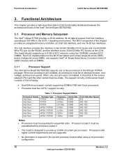
...; Server Board SE7505VB2. 3.1 Processor and Memory Subsystem The Intel® chipset E7505 provides a 36-bit address, 64-bit data processor host bus interface, operating at 533 MHz in the 604-pin FCPGA package. Processor Support Matrix Processor Family Package Type Intel Xeon FCPGA Intel Xeon FCPGA Intel Xeon FCPGA Intel Xeon mPGA / FCPGA Intel Xeon mPGA / FCPGA Intel Xeon mPGA...
...; Server Board SE7505VB2. 3.1 Processor and Memory Subsystem The Intel® chipset E7505 provides a 36-bit address, 64-bit data processor host bus interface, operating at 533 MHz in the 604-pin FCPGA package. Processor Support Matrix Processor Family Package Type Intel Xeon FCPGA Intel Xeon FCPGA Intel Xeon FCPGA Intel Xeon mPGA / FCPGA Intel Xeon mPGA / FCPGA Intel Xeon mPGA...
Product Specification
Page 17
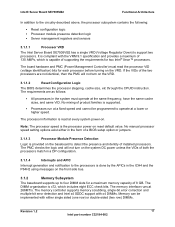
...contains the following: Reset configuration logic Processor module presence detection logic Server management registers and sensors 3.1.1.1 Processor VRD The Intel Server Board SE7505VB2 has a single VRD (Voltage Regulator Down) to operate at 266MT/s. It is the processor power on the VRD....each processor before turning on reset default value. The memory controller supports memory scrubbing, single-bit error correction and multiple-bit error detection and Intel x4 SDDC support with x4 DIMMs. Memory can be programmed to support two processors. Note: The processor speed is compliant...
...contains the following: Reset configuration logic Processor module presence detection logic Server management registers and sensors 3.1.1.1 Processor VRD The Intel Server Board SE7505VB2 has a single VRD (Voltage Regulator Down) to operate at 266MT/s. It is the processor power on the VRD....each processor before turning on reset default value. The memory controller supports memory scrubbing, single-bit error correction and multiple-bit error detection and Intel x4 SDDC support with x4 DIMMs. Memory can be programmed to support two processors. Note: The processor speed is compliant...
Product Specification
Page 18
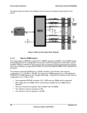
... 3.1.2.1 Memory DIMM Support The board supports DDR266-compliant ECC DIMMS operating at http://support.intel.com/support/motherboards/server/se7505vb2. A list of the memory sub-system implemented on this board. Only registered DDR266 compliant, ECC, DDR memory DIMMs will be supported ECC single-bit errors (SBE) will be corrected and multiple-bit error (MBE) will be detected. Functional Architecture Intel®...
... 3.1.2.1 Memory DIMM Support The board supports DDR266-compliant ECC DIMMS operating at http://support.intel.com/support/motherboards/server/se7505vb2. A list of the memory sub-system implemented on this board. Only registered DDR266 compliant, ECC, DDR memory DIMMs will be supported ECC single-bit errors (SBE) will be corrected and multiple-bit error (MBE) will be detected. Functional Architecture Intel®...
Product Specification
Page 19
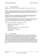
... and stacked 1GB (low profile) DIMMs are two banks of these size memory parts, contact Intel Customer Support and request the SE7505VB2 server board memory cooling duct, part number C28482001. Intel® Server Board SE7505VB2 Functional Architecture 3.1.2.2 Memory Configuration The memory interface between populated DIMMs. DIMM and memory configurations must be populated in order. Before populating either of DIMMs, labeled...
... and stacked 1GB (low profile) DIMMs are two banks of these size memory parts, contact Intel Customer Support and request the SE7505VB2 server board memory cooling duct, part number C28482001. Intel® Server Board SE7505VB2 Functional Architecture 3.1.2.2 Memory Configuration The memory interface between populated DIMMs. DIMM and memory configurations must be populated in order. Before populating either of DIMMs, labeled...
Product Specification
Page 22
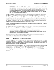
... provided PCI buses. Functional Architecture Intel® Server Board SE7505VB2 ICH4: I /O. The ICH4 controller has several components. The P64H2 translates the HI 2.0 bus operation to support low speed legacy I /O Controller Hub 4. The memory interface supports a 72-bit or 144-bit wide memory array. The ICH4 can support a maximum of 8 GB of DDR266 memory using 2 GB DIMMs. This configuration...
... provided PCI buses. Functional Architecture Intel® Server Board SE7505VB2 ICH4: I /O. The ICH4 controller has several components. The P64H2 translates the HI 2.0 bus operation to support low speed legacy I /O Controller Hub 4. The memory interface supports a 72-bit or 144-bit wide memory array. The ICH4 can support a maximum of 8 GB of DDR266 memory using 2 GB DIMMs. This configuration...
Product Specification
Page 23
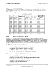
... features provided by the MCH include the following: Full support of ECC on the processor bus Full support of registered DDR266 ECC DIMMs. Support for 2 GB DDR memory modules Memory scrubbing Revision 1.2 23 Intel part number C32194-002 In addition, the MCH incorporates a hub interface (HI) . Intel® Server Board SE7505VB2 Functional Architecture 3.2.1.1 DDR Configurations The DDR interface...
... features provided by the MCH include the following: Full support of ECC on the processor bus Full support of registered DDR266 ECC DIMMs. Support for 2 GB DDR memory modules Memory scrubbing Revision 1.2 23 Intel part number C32194-002 In addition, the MCH incorporates a hub interface (HI) . Intel® Server Board SE7505VB2 Functional Architecture 3.2.1.1 DDR Configurations The DDR interface...
Product Specification
Page 25
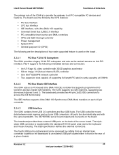
... memory and up to access the IDE functionality. The triplestack USB connector is located within the standard ATX I /O devices and features. Revision 1.2 25 Intel part number C32194-002 The ICH4 supports two IDE channels, supporting two drives each 40-pin connector. 3.2.4.3 USB Interface The ICH4 contains three USB 2.0 controllers and four USB hubs. The SE7505VB2...
... memory and up to access the IDE functionality. The triplestack USB connector is located within the standard ATX I /O devices and features. Revision 1.2 25 Intel part number C32194-002 The ICH4 supports two IDE channels, supporting two drives each 40-pin connector. 3.2.4.3 USB Interface The ICH4 contains three USB 2.0 controllers and four USB hubs. The SE7505VB2...
Product Specification
Page 36
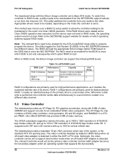
...supports a variety of a Clear CMOS operation. Optionally, the video controller can support...systems support RAID mode. Refer to the SE7505VB2 support website... of video SDRAM and support circuitry for high performance ... in the standard ATX I /O Subsystem Intel® Server Board SE7505VB2 The baseboard ships with 8 MB of ...support dual monitor mode when an off -board video adapter is set to the other. PCI I /O opening area. It supports... be downloaded from the SE7505VB2 support website or run from... SSID that supports this functionality. 36 Revision 1.2 Intel part number C32194...
...supports a variety of a Clear CMOS operation. Optionally, the video controller can support...systems support RAID mode. Refer to the SE7505VB2 support website... of video SDRAM and support circuitry for high performance ... in the standard ATX I /O Subsystem Intel® Server Board SE7505VB2 The baseboard ships with 8 MB of ...support dual monitor mode when an off -board video adapter is set to the other. PCI I /O opening area. It supports... be downloaded from the SE7505VB2 support website or run from... SSID that supports this functionality. 36 Revision 1.2 Intel part number C32194...
Product Specification
Page 37
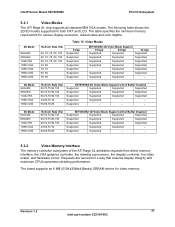
...,72,75,90,100 43,60,70,72 60,66,76,85 SE7505VB2 3D Video Mode Support with Z Buffer Enabled Supported Supported Supported Supported Supported Supported Supported Supported Supported Supported Supported Supported Supported Supported - - The table specifies the minimum memory requirement for video memory. Intel® Server Board SE7505VB2 PCI I/O Subsystem 5.3.1 Video Modes The ATI Rage XL chip supports all standard IBM VGA modes. The following table shows the 2D/3D...
...,72,75,90,100 43,60,70,72 60,66,76,85 SE7505VB2 3D Video Mode Support with Z Buffer Enabled Supported Supported Supported Supported Supported Supported Supported Supported Supported Supported Supported Supported Supported Supported - - The table specifies the minimum memory requirement for video memory. Intel® Server Board SE7505VB2 PCI I/O Subsystem 5.3.1 Video Modes The ATI Rage XL chip supports all standard IBM VGA modes. The following table shows the 2D/3D...
Product Specification
Page 51
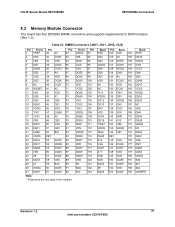
Intel® Server Board SE7505VB2 SE7505VB2 Connectors 8.2 Memory Module Connector The board has four DDR266 DIMM connectors and supports registered ECC DDR modules (Rev 1.0). Table 23. Front VDDQ /WE DQ41 /CAS VSS DQS5 DQ42 DQ43 VDD */CS2 DQ48 DQ49 VSS */CK2 *CK2 VDDQ DQS6 ... NC 174 DQ60 175 DQ61 176 VSS 177 DM7 178 DQ62 179 DQ63 180 VDDQ 181 SA0 182 SA1 183 SA2 184 VDDSPD Revision 1.2 51 Intel part number C32194-002 DIMM Connectors (J9H1, J9J1, J9H2, J9J2) Pin Front Pin Front Pin 1 VREF 32 A5 62 2 DQ0 33 DQ24 63 3 VSS 34...
Intel® Server Board SE7505VB2 SE7505VB2 Connectors 8.2 Memory Module Connector The board has four DDR266 DIMM connectors and supports registered ECC DDR modules (Rev 1.0). Table 23. Front VDDQ /WE DQ41 /CAS VSS DQS5 DQ42 DQ43 VDD */CS2 DQ48 DQ49 VSS */CK2 *CK2 VDDQ DQS6 ... NC 174 DQ60 175 DQ61 176 VSS 177 DM7 178 DQ62 179 DQ63 180 VDDQ 181 SA0 182 SA1 183 SA2 184 VDDSPD Revision 1.2 51 Intel part number C32194-002 DIMM Connectors (J9H1, J9J1, J9H2, J9J2) Pin Front Pin Front Pin 1 VREF 32 A5 62 2 DQ0 33 DQ24 63 3 VSS 34...
Product Specification
Page 81
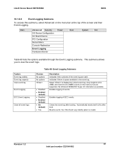
...Monitor Power Boot System Exit Table 60 lists the options available through the Event Logging submenu. Intel® Server Board SE7505VB2 BIOS 10.1.6.6 Event Logging Submenu To access this submenu, select Advanced on the memory bus are valid. Only single bit error (SBE) and multi bit error (MBE) events... on the menu bar at the top of the event log are supported. This submenu allows you ...
...Monitor Power Boot System Exit Table 60 lists the options available through the Event Logging submenu. Intel® Server Board SE7505VB2 BIOS 10.1.6.6 Event Logging Submenu To access this submenu, select Advanced on the memory bus are valid. Only single bit error (SBE) and multi bit error (MBE) events... on the menu bar at the top of the event log are supported. This submenu allows you ...
Product Specification
Page 88
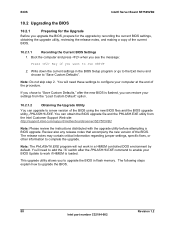
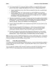
... Default" option. 10.2.1.2 Obtaining the Upgrade Utility You can obtain the BIOS upgrade file and the PHLASH.EXE utility from the Intel Customer Support Web site: http://support.intel.com/support/motherboards/server/SE7505VB2 Note: Please review the instructions distributed with the upgrade utility before attempting a BIOS upgrade. Note: The PHLASH16.EXE program will ... and making a copy of the BIOS. Boot the computer and press when you see the message: Press Key if you to work in flash memory. This upgrade utility allows you want to upgrade the BIOS. 88 Revision...
... Default" option. 10.2.1.2 Obtaining the Upgrade Utility You can obtain the BIOS upgrade file and the PHLASH.EXE utility from the Intel Customer Support Web site: http://support.intel.com/support/motherboards/server/SE7505VB2 Note: Please review the instructions distributed with the upgrade utility before attempting a BIOS upgrade. Note: The PHLASH16.EXE program will ... and making a copy of the BIOS. Boot the computer and press when you see the message: Press Key if you to work in flash memory. This upgrade utility allows you want to upgrade the BIOS. 88 Revision...
Product Specification
Page 90
... saved your settings, and exit Setup. 10.2.3 Crisis Recovery Diskette It is completed. Press F10 and to update the flash memory, you that says "Completed Successfully." however, a recovery disk should reset automatically when the BIOS update process is unlikely that anything... down the system during boot. The system should be updated. Remove the diskette from the Intel Customer Support Web site: http://support.intel.com/support/motherboards/server/SE7505VB2 90 Revision 1.2 Intel part number C32194-002 Enter Setup by choosing from the Exit menu, the Load Custom Defaults...
... saved your settings, and exit Setup. 10.2.3 Crisis Recovery Diskette It is completed. Press F10 and to update the flash memory, you that says "Completed Successfully." however, a recovery disk should reset automatically when the BIOS update process is unlikely that anything... down the system during boot. The system should be updated. Remove the diskette from the Intel Customer Support Web site: http://support.intel.com/support/motherboards/server/SE7505VB2 90 Revision 1.2 Intel part number C32194-002 Enter Setup by choosing from the Exit menu, the Load Custom Defaults...

Product Specification
Page 93
...93 Intel part number C32194-002 POST Error Beep Codes Beeps 4-3-1-2 4-3-1-3 4-3-1-4 4-3-3-1 4-3-3-2 4-3-3-3 4-3-3-4 4-3-4-1 4-3-4-2 4-3-4-3 1-3-4-3 Reason No memory DIMM(s) Memory type is a table of space in the BIOS to 4MB 10.3.2 BIOS Event Log The SE7505VB2 ...contains a small amount of these events and their meaning: Table 68. Below is mismatch No DIMM Pair(s) in System Memory Error Row Address Bits Memory Error Internal Banks Memory Error Timing Memory Error Register CAS 3 Memory Error Register NonReg Mix Memory Error CAS Latency Memory Error Size Not Supported Memory...
...93 Intel part number C32194-002 POST Error Beep Codes Beeps 4-3-1-2 4-3-1-3 4-3-1-4 4-3-3-1 4-3-3-2 4-3-3-3 4-3-3-4 4-3-4-1 4-3-4-2 4-3-4-3 1-3-4-3 Reason No memory DIMM(s) Memory type is a table of space in the BIOS to 4MB 10.3.2 BIOS Event Log The SE7505VB2 ...contains a small amount of these events and their meaning: Table 68. Below is mismatch No DIMM Pair(s) in System Memory Error Row Address Bits Memory Error Internal Banks Memory Error Timing Memory Error Register CAS 3 Memory Error Register NonReg Mix Memory Error CAS Latency Memory Error Size Not Supported Memory...


