
Product Guide
Page 32
...LAN* (WOL)) and 12+ V CPU power support [ATX], which meets the SSI EPS 12 V specification. You must meet the following minimum requirements. For a complete list of supported processors, see : http://support.intel.com/support/motherboards/server/SE7501HG2 Processor Minimum of 450 W with 1.2... A +5 V standby current (in the Intel® Server Chassis SC5200 with 512K cache. Minimum Hardware Requirements To avoid ...
...LAN* (WOL)) and 12+ V CPU power support [ATX], which meets the SSI EPS 12 V specification. You must meet the following minimum requirements. For a complete list of supported processors, see : http://support.intel.com/support/motherboards/server/SE7501HG2 Processor Minimum of 450 W with 1.2... A +5 V standby current (in the Intel® Server Chassis SC5200 with 512K cache. Minimum Hardware Requirements To avoid ...

Product Guide
Page 44
... into place on the fan assembly (Figure 15, 3) will be from front to back. Attach CPU Fan 1 cable to the Retention Mechanism ✏ NOTE System airflow must be side by side. 44 Intel Server Board SE7501HG2 Product Guide Make sure the PWT is aligned so the fan is toward the front of..., 1. The tabs on the OUTSIDE of the retention mechanism apart slightly. Attaching the Top Assembly to the server board at location J7F1 and/or attach CPU Fan 2 cable at the sides of the retention mechanism (Figure 15, 2). 15. Pull out on the tabs located at the bottom of the chassis...
... into place on the fan assembly (Figure 15, 3) will be from front to back. Attach CPU Fan 1 cable to the Retention Mechanism ✏ NOTE System airflow must be side by side. 44 Intel Server Board SE7501HG2 Product Guide Make sure the PWT is aligned so the fan is toward the front of..., 1. The tabs on the OUTSIDE of the retention mechanism apart slightly. Attaching the Top Assembly to the server board at location J7F1 and/or attach CPU Fan 2 cable at the sides of the retention mechanism (Figure 15, 2). 15. Pull out on the tabs located at the bottom of the chassis...

Product Guide
Page 51
... chassis that socket levers are installed. All DIMMs must be installed in the slot. 3. Check that require the PWT assembly, reattach the CPU fan. No DIMM mixing is used only if 400 MHz processors are securely latched. 2 DDR200 compliant registered ECC DIMMs can be used ,... Upgrades 51 Open both DIMM socket levers. 2. Pull the tabs at the bottom of supported memory, visit the Intel Support website: http://support.intel.com/support/motherboards/server/SE7501HG2 1. For chassis that require the PWT assembly (SC5200 Base chassis and reference chassis), reattach the fan assembly to ...
... chassis that socket levers are installed. All DIMMs must be installed in the slot. 3. Check that require the PWT assembly, reattach the CPU fan. No DIMM mixing is used only if 400 MHz processors are securely latched. 2 DDR200 compliant registered ECC DIMMs can be used ,... Upgrades 51 Open both DIMM socket levers. 2. Pull the tabs at the bottom of supported memory, visit the Intel Support website: http://support.intel.com/support/motherboards/server/SE7501HG2 1. For chassis that require the PWT assembly (SC5200 Base chassis and reference chassis), reattach the fan assembly to ...

Product Guide
Page 54
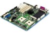
Making Connections to the Server Board 54 Intel Server Board SE7501HG2 Product Guide Making Connections to the Server Board A B C 12 V D L E F G K J A I T H SCSI A 1 0 0 A Aux Power B Main Power C +12 V CPU Power D CPU1 Fan (top), CPU2 fan (bottom) E Floppy Disk Drive Connector F System Fan 5 (top), System Fan 4 (bottom) TP00030 G System Fan 3 H Front Panel Connector I Primary IDE (top), Secondary IDE (bottom) J SCSI Channel A (left), SCSI Channel B (right) K Chassis Intrusion L System Fan 1 (top), System Fan 2 (bottom) Figure 28.
Making Connections to the Server Board 54 Intel Server Board SE7501HG2 Product Guide Making Connections to the Server Board A B C 12 V D L E F G K J A I T H SCSI A 1 0 0 A Aux Power B Main Power C +12 V CPU Power D CPU1 Fan (top), CPU2 fan (bottom) E Floppy Disk Drive Connector F System Fan 5 (top), System Fan 4 (bottom) TP00030 G System Fan 3 H Front Panel Connector I Primary IDE (top), Secondary IDE (bottom) J SCSI Channel A (left), SCSI Channel B (right) K Chassis Intrusion L System Fan 1 (top), System Fan 2 (bottom) Figure 28.

Product Guide
Page 66
...transfers. It displays the method of moving data to and from the hard drive. It is informational only. Table 10. Reports the CPU ID for processor 1. Reports the L2 cache size for processor 2. Ultra DMA Mode Mode 2 Mode 4 This field is disabled. When...from the hard drive. This field specifies the number of moving data to Disabled upon booting. Reports the CPU ID for processor 2. 66 Intel Server Board SE7501HG2 Product Guide Processor Settings Submenu Feature Choices Processor POST Speed Information Only Processor Retest Enabled Disabled Hyper-Threading ...
...transfers. It displays the method of moving data to and from the hard drive. It is informational only. Table 10. Reports the CPU ID for processor 1. Reports the L2 cache size for processor 2. Ultra DMA Mode Mode 2 Mode 4 This field is disabled. When...from the hard drive. This field specifies the number of moving data to Disabled upon booting. Reports the CPU ID for processor 2. 66 Intel Server Board SE7501HG2 Product Guide Processor Settings Submenu Feature Choices Processor POST Speed Information Only Processor Retest Enabled Disabled Hyper-Threading ...

Product Guide
Page 135
... one-time change, 62 boot sequence booting without keyboard, 27 selecting, 88 setting in Setup, 27 booting cold, 111 bumper how to install, 37 cable CPU fan, 45, 51 Caution avoid touching processor pins, 39 selecting correct processor, 39 Chassis intrusion, 30 chipset, 9 Client System Setup Utility, 81 CMOS, 62, 81...
... one-time change, 62 boot sequence booting without keyboard, 27 selecting, 88 setting in Setup, 27 booting cold, 111 bumper how to install, 37 cable CPU fan, 45, 51 Caution avoid touching processor pins, 39 selecting correct processor, 39 Chassis intrusion, 30 chipset, 9 Client System Setup Utility, 81 CMOS, 62, 81...
Product Guide
Page 136
Controller, 113 IDE, 19 Memory, 16 CPU fan cable install, 45 removing, 51 CSSU, 81 device driver how to create diskettes, 104 diagnostics preparing system for testing, 113 DIMM install, 52 mixed, ... HI 2.0 bus interface, 13 Hot Key, 89 hot key option quick reference, 79 Hot keys, 28 I/O PCI expansion slots, 9 ports provided, 10 I/O shield, 33, 45 Intel Server Board SE7501HG2 Product Guide
Controller, 113 IDE, 19 Memory, 16 CPU fan cable install, 45 removing, 51 CSSU, 81 device driver how to create diskettes, 104 diagnostics preparing system for testing, 113 DIMM install, 52 mixed, ... HI 2.0 bus interface, 13 Hot Key, 89 hot key option quick reference, 79 Hot keys, 28 I/O PCI expansion slots, 9 ports provided, 10 I/O shield, 33, 45 Intel Server Board SE7501HG2 Product Guide


