
User Guide
Page 9
... vii Wichtige Sicherheitshinweise vii Consignes de sécurité ...vii Instrucciones de seguridad importantes vii Warnings...viii Server Board Features 1 Connector and Header Locations 4 Configuration Jumpers ...5 Back Panel Connectors ...6 Hardware Requirements ...7 Processor ...7 Memory ...7 Power Supply ...8 Optional Hardware ...8 Hard Disk Drives ...8 Server Utilities ...9 Using the...the Processor ...15 Installing the Active Heat Sink 18 Installing the Passive Heat Sink 19 Intel® Server Board SE7230NH1-E and Intel® Server Platform SR1475NH1-E User's Guide ix
... vii Wichtige Sicherheitshinweise vii Consignes de sécurité ...vii Instrucciones de seguridad importantes vii Warnings...viii Server Board Features 1 Connector and Header Locations 4 Configuration Jumpers ...5 Back Panel Connectors ...6 Hardware Requirements ...7 Processor ...7 Memory ...7 Power Supply ...8 Optional Hardware ...8 Hard Disk Drives ...8 Server Utilities ...9 Using the...the Processor ...15 Installing the Active Heat Sink 18 Installing the Passive Heat Sink 19 Intel® Server Board SE7230NH1-E and Intel® Server Platform SR1475NH1-E User's Guide ix
User Guide
Page 18
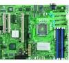
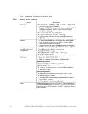
... 2.0 ports • One DH10 Serial A header • Two SATA-150 connectors with integrated RAID 0/1 support • One ATA-100 connector • SSI-compliant 34-pin control panel header Integrated stand-alone ATI ES1000 graphics engine that supports standard SVGA drivers with ...; RJ45 Serial B port • Two RJ45 NIC connectors for a total of the server board. Table 1. Table 1 summarizes the features of 4 DIMMs (2 DIMMs / Channel) providing up to support the onboard video controller 2 Intel® Server Board SE7230NH1-E and Intel® Server Platform SR1475NH1-E User's Guide
... 2.0 ports • One DH10 Serial A header • Two SATA-150 connectors with integrated RAID 0/1 support • One ATA-100 connector • SSI-compliant 34-pin control panel header Integrated stand-alone ATI ES1000 graphics engine that supports standard SVGA drivers with ...; RJ45 Serial B port • Two RJ45 NIC connectors for a total of the server board. Table 1. Table 1 summarizes the features of 4 DIMMs (2 DIMMs / Channel) providing up to support the onboard video controller 2 Intel® Server Board SE7230NH1-E and Intel® Server Platform SR1475NH1-E User's Guide
User Guide
Page 20
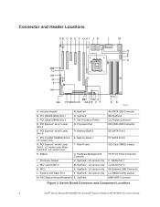
... Port 2 GG.Clear CMOS Jumper HH.Front Panel Connector II. Hardware Management Controller I J K L M N O P Q MM LL KK JJ II HH BB Y W U GG FF EE DD CC AA Z X V T SR TP01781 A. LX version only J. SysFan6 - PS2 Stacked Mouse/Keyboard Z. Server Board Connector and Component Locations 4 Intel® Server Board SE7230NH1-E and Intel® Server Platform SR1475NH1-E User's Guide Processor...
... Port 2 GG.Clear CMOS Jumper HH.Front Panel Connector II. Hardware Management Controller I J K L M N O P Q MM LL KK JJ II HH BB Y W U GG FF EE DD CC AA Z X V T SR TP01781 A. LX version only J. SysFan6 - PS2 Stacked Mouse/Keyboard Z. Server Board Connector and Component Locations 4 Intel® Server Board SE7230NH1-E and Intel® Server Platform SR1475NH1-E User's Guide Processor...

User Guide
Page 22
NIC2 (10/100/1000Mb) E. NIC1 (10/100/1000Mb) F. Table 3. Back Panel Connectors E B A C D A. Serial A C. LED Information LED Left Right LED State Off Solid Amber Blinking Amber Off Solid Amber Solid Green Description No network connection Network connection in ... the following information. Video D. USB1-2 F TP01783 The NIC LEDs at the right and left LED is on or blinking) 100 Mbps connection 1000 Mbps connection 6 Intel® Server Board SE7230NH1-E and Intel® Server Platform SR1475NH1-E User's Guide Stacked PS2 Mouse/Keyboard Ports B.
NIC2 (10/100/1000Mb) E. NIC1 (10/100/1000Mb) F. Table 3. Back Panel Connectors E B A C D A. Serial A C. LED Information LED Left Right LED State Off Solid Amber Blinking Amber Off Solid Amber Solid Green Description No network connection Network connection in ... the following information. Video D. USB1-2 F TP01783 The NIC LEDs at the right and left LED is on or blinking) 100 Mbps connection 1000 Mbps connection 6 Intel® Server Board SE7230NH1-E and Intel® Server Platform SR1475NH1-E User's Guide Stacked PS2 Mouse/Keyboard Ports B.

User Guide
Page 43
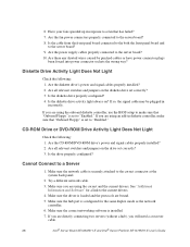
...the system cooling fans are not operating properly, it is fully seated in the server board connector. • Reboot the system for help. Check the following : 1. If not, see ... processor(s) and re-seat them . 12. See the manufacturer's documentation. 2. Intel® Server Board SE7230NH1-E and Intel® Server Platform SR1475NH1-E User's Guide 27 Make sure the processor(s) comply with... Are the video monitor's signal and power cables properly installed? 3. Have any other front panel LEDs lit? 4. Make sure the processor(s) have been populated according to check the fan ...
...the system cooling fans are not operating properly, it is fully seated in the server board connector. • Reboot the system for help. Check the following : 1. If not, see ... processor(s) and re-seat them . 12. See the manufacturer's documentation. 2. Intel® Server Board SE7230NH1-E and Intel® Server Platform SR1475NH1-E User's Guide 27 Make sure the processor(s) comply with... Are the video monitor's signal and power cables properly installed? 3. Have any other front panel LEDs lit? 4. Make sure the processor(s) have been populated according to check the fan ...
User Guide
Page 44
...by pinched-cables or have power connector plugs been forced into power connector sockets the wrong way? If so, the signal cable may be plugged in response to "Disabled." If you will need a crossover cable. 28 Intel® Server Board SE7230NH1-E and Intel® Server Platform SR1475NH1-E User...driver is securely attached to the current drivers. 4. Make sure the correct networking software is configured for a link to the correct connector at the system back panel. 2. Are all relevant switches and jumpers on ? 6. Are the CD-ROM/DVD-ROM drive's power and signal cables properly...
...by pinched-cables or have power connector plugs been forced into power connector sockets the wrong way? If so, the signal cable may be plugged in response to "Disabled." If you will need a crossover cable. 28 Intel® Server Board SE7230NH1-E and Intel® Server Platform SR1475NH1-E User...driver is securely attached to the current drivers. 4. Make sure the correct networking software is configured for a link to the correct connector at the system back panel. 2. Are all relevant switches and jumpers on ? 6. Are the CD-ROM/DVD-ROM drive's power and signal cables properly...

User Guide
Page 45
...Turn off with the AC power cord plugged in your PCI card(s) for a link to the NIC connectors. The controller stopped working without apparent cause. 1. Make sure your operating system supports shared interrupts. 4. ...you have turned the system power off the server power by using the power button on the front panel. For these drivers, it may require interrupts that came with other adapter supports shared interrupts. then try...to alter settings so that interrupts are not shared. Intel® Server Board SE7230NH1-E and Intel® Server Platform SR1475NH1-E User's Guide 29
...Turn off with the AC power cord plugged in your PCI card(s) for a link to the NIC connectors. The controller stopped working without apparent cause. 1. Make sure your operating system supports shared interrupts. 4. ...you have turned the system power off the server power by using the power button on the front panel. For these drivers, it may require interrupts that came with other adapter supports shared interrupts. then try...to alter settings so that interrupts are not shared. Intel® Server Board SE7230NH1-E and Intel® Server Platform SR1475NH1-E User's Guide 29


