Product Guide
Page 1
Intel® Server Board S875WP1-E Product Guide A Guide for Technically Qualified Assemblers of Intel® Identified Subassemblies/Products Order Number: C32693-002
Intel® Server Board S875WP1-E Product Guide A Guide for Technically Qualified Assemblers of Intel® Identified Subassemblies/Products Order Number: C32693-002
Product Guide
Page 2
... time, without prior written consent of others. Intel makes no responsibility for a particular purpose. ii See also Intel Server Boards and Server Chassis Safety Information on the Resource CD and/or at any means without notice. Intel assumes no commitment to update nor to documentation ...and product descriptions at http:\\support.intel.com. No part of this material,...
... time, without prior written consent of others. Intel makes no responsibility for a particular purpose. ii See also Intel Server Boards and Server Chassis Safety Information on the Resource CD and/or at any means without notice. Intel assumes no commitment to update nor to documentation ...and product descriptions at http:\\support.intel.com. No part of this material,...
Product Guide
Page 3
Contents 1 Server Board Features 9 Server Board Connector and Component Locations 11 Back Panel Connectors 12 Front Panel Connectors 12 Processor ...13 Memory ...13 Intel 875P Chipset...14 Intel 82875P Memory Controller Hub (MCH 14 Intel 82801EB I/O Controller Hub (ICH5-R 15 Intel 82802AC Firmware Hub (FWH 15 Video ...15 AGP ......19 PCI I/O Subsystem...20 32-bit, 33-MHz PCI Subsystem 20 Device IDs (IDSEL 21 Data Storage ...21 Serial ATA (SATA) ...21 IDE Interfaces ...22 SCSI Hard Drive Activity LED Connector 22 Network Interface Controller (NIC 23 NIC Connector and Status LEDs ...
Contents 1 Server Board Features 9 Server Board Connector and Component Locations 11 Back Panel Connectors 12 Front Panel Connectors 12 Processor ...13 Memory ...13 Intel 875P Chipset...14 Intel 82875P Memory Controller Hub (MCH 14 Intel 82801EB I/O Controller Hub (ICH5-R 15 Intel 82802AC Firmware Hub (FWH 15 Video ...15 AGP ......19 PCI I/O Subsystem...20 32-bit, 33-MHz PCI Subsystem 20 Device IDs (IDSEL 21 Data Storage ...21 Serial ATA (SATA) ...21 IDE Interfaces ...22 SCSI Hard Drive Activity LED Connector 22 Network Interface Controller (NIC 23 NIC Connector and Status LEDs ...
Product Guide
Page 4
...Disclaimer 39 Warnings and Cautions...39 Installing the I/O Shield ...41 Installing Chassis Standoffs 42 Intel Server Chassis SC5200 42 Intel® Server Chassis SC5250-E 43 Installing the Server Board...44 Placing the Server Board into the Chassis 44 Attaching the Server Board 44 Installing the Processor...45 Removing the Processor...48 Installing and Removing Memory 49 DIMM Installation... ...58 Chassis Intrusion...58 Connecting Power Cables 58 Setting the BIOS Configuration Jumper 58 Clearing Passwords ...59 Replacing the Battery...60 iv Intel Server Board S875WP1-E Product Guide
...Disclaimer 39 Warnings and Cautions...39 Installing the I/O Shield ...41 Installing Chassis Standoffs 42 Intel Server Chassis SC5200 42 Intel® Server Chassis SC5250-E 43 Installing the Server Board...44 Placing the Server Board into the Chassis 44 Attaching the Server Board 44 Installing the Processor...45 Removing the Processor...48 Installing and Removing Memory 49 DIMM Installation... ...58 Chassis Intrusion...58 Connecting Power Cables 58 Setting the BIOS Configuration Jumper 58 Clearing Passwords ...59 Replacing the Battery...60 iv Intel Server Board S875WP1-E Product Guide
Product Guide
Page 5
3 Configuration Software and Utilities 63 Updating the BIOS with the Intel® Flash Memory Update Utility 63 Obtaining the BIOS Update File 63 Recording the Current BIOS Settings 64 Creating Bootable Media 64 Creating a BIOS Update ... ...93 4 Solving BIOS Problems 95 BIOS Beep Codes...95 BIOS Error Messages ...96 5 Getting Help 99 World Wide Web ...99 Telephone ...99 6 Technical Reference 101 Server Board Connectors...101 Baseboard Connectors 102 Power, Fan, Chassis Intrusion Connectors 102 Add-In...
3 Configuration Software and Utilities 63 Updating the BIOS with the Intel® Flash Memory Update Utility 63 Obtaining the BIOS Update File 63 Recording the Current BIOS Settings 64 Creating Bootable Media 64 Creating a BIOS Update ... ...93 4 Solving BIOS Problems 95 BIOS Beep Codes...95 BIOS Error Messages ...96 5 Getting Help 99 World Wide Web ...99 Telephone ...99 6 Technical Reference 101 Server Board Connectors...101 Baseboard Connectors 102 Power, Fan, Chassis Intrusion Connectors 102 Add-In...
Product Guide
Page 6
Server Board Resources...104 Memory Map ...104 DMA Channels ...104 I/O Map ...105 Interrupts ...106 7 Regulatory and Integration Information 107 Product Regulatory Compliance 107 Product Safety Compliance 107 ... / New Zealand 110 Installation Precautions ...111 Installation Requirements...111 Prevent Power Supply Overload 111 Place Battery Marking 112 Use Only for Intended Applications 112 vi Intel Server Board S875WP1-E Product Guide
Server Board Resources...104 Memory Map ...104 DMA Channels ...104 I/O Map ...105 Interrupts ...106 7 Regulatory and Integration Information 107 Product Regulatory Compliance 107 Product Safety Compliance 107 ... / New Zealand 110 Installation Precautions ...111 Installation Requirements...111 Prevent Power Supply Overload 111 Place Battery Marking 112 Use Only for Intended Applications 112 vi Intel Server Board S875WP1-E Product Guide
Product Guide
Page 7
... 8. Table 12. Back Panel Connectors 12 Figure 3. Installing the I/O Shield 41 Figure 7. Connecting the SATA Cable 54 Figure 20. Table 2. Table 18. Placing the Server Board into the Chassis 44 Figure 10. Table 3. Table 7. Table 15. Connecting the Processor Fan Cable to... the Processor Socket 47 Figure 15. Removing the Battery 62 Figure 24. Figures Figure 1. Server Board Components 11 Figure 2. Location of the Standby Power Indicator LED CR7J1 29 Figure 5. Installing Chassis Standoffs in the Processor Socket ...
... 8. Table 12. Back Panel Connectors 12 Figure 3. Installing the I/O Shield 41 Figure 7. Connecting the SATA Cable 54 Figure 20. Table 2. Table 18. Placing the Server Board into the Chassis 44 Figure 10. Table 3. Table 7. Table 15. Connecting the Processor Fan Cable to... the Processor Socket 47 Figure 15. Removing the Battery 62 Figure 24. Figures Figure 1. Server Board Components 11 Figure 2. Location of the Standby Power Indicator LED CR7J1 29 Figure 5. Installing Chassis Standoffs in the Processor Socket ...
Product Guide
Page 9
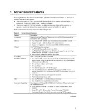
... six High- Server Board Features Feature Description Processors Support for an Intel® Pentium® 4 processor in two options: • The server board S875WP1 includes dual-channel Serial ATA support with support for RAID 0 and 1 support is available in an mPGA478 package with an 800/533/400 MHz system bus Memory • Four 184-pin DDR SDRAM Dual...
... six High- Server Board Features Feature Description Processors Support for an Intel® Pentium® 4 processor in two options: • The server board S875WP1 includes dual-channel Serial ATA support with support for RAID 0 and 1 support is available in an mPGA478 package with an 800/533/400 MHz system bus Memory • Four 184-pin DDR SDRAM Dual...
Product Guide
Page 10
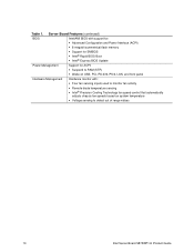
... Hardware Management Hardware monitor with: • Four fan sensing inputs used to monitor fan activity • Remote diode temperature sensing • Intel® Precision Cooling Technology fan speed control that automatically adjusts chassis fan speeds based on system temperature • Voltage sensing to detect out of range values 10 Intel Server Board S875WP1-E Product Guide
... Hardware Management Hardware monitor with: • Four fan sensing inputs used to monitor fan activity • Remote diode temperature sensing • Intel® Precision Cooling Technology fan speed control that automatically adjusts chassis fan speeds based on system temperature • Voltage sensing to detect out of range values 10 Intel Server Board S875WP1-E Product Guide
Product Guide
Page 11
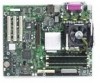
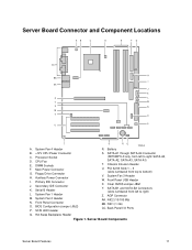
...Server Board Components Server Board Features 11 CPU Fan E. System Fan 2 Header N. SCSI LED Header S. PCI 32/33 Slots 1 - 3 (slots numbered from left to right) Z. NIC1 (1 Gb) CC. Back Panel I . Battery RQ TP00182 B. +12V CPU Power Connector C. SATA-A1 through SATA-A4 Connector (S875WP1LX only, from top to right: SATA-A4, SATA-A2, SATA-A3, SATA... Socket D. Main Power Connector G. SATA-B1 and SATA-B2 Connectors (slots numbered from left to bottom) V. Floppy Drive Connector H. BIOS Configuration Jumper (J8J2) P. Server Board Connector and Component Locations AB C ...
...Server Board Components Server Board Features 11 CPU Fan E. System Fan 2 Header N. SCSI LED Header S. PCI 32/33 Slots 1 - 3 (slots numbered from left to right) Z. NIC1 (1 Gb) CC. Back Panel I . Battery RQ TP00182 B. +12V CPU Power Connector C. SATA-A1 through SATA-A4 Connector (S875WP1LX only, from top to right: SATA-A4, SATA-A2, SATA-A3, SATA... Socket D. Main Power Connector G. SATA-B1 and SATA-B2 Connectors (slots numbered from left to bottom) V. Floppy Drive Connector H. BIOS Configuration Jumper (J8J2) P. Server Board Connector and Component Locations AB C ...
Product Guide
Page 13
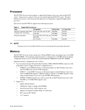
...-plated contacts. The server board S875WP1-E supports the following processors. Supported memory configuration are as follows: • Up to the server board through the mPGA478 socket. The processor connects to four dual-channel 184-pin Double Data Rate (DDR) SDRAM DIMMs connectors with the server board and must be purchased separately. Processor The S875WP1-E server board supports a single Intel Pentium 4 processor with...
...-plated contacts. The server board S875WP1-E supports the following processors. Supported memory configuration are as follows: • Up to the server board through the mPGA478 socket. The processor connects to four dual-channel 184-pin Double Data Rate (DDR) SDRAM DIMMs connectors with the server board and must be purchased separately. Processor The S875WP1-E server board supports a single Intel Pentium 4 processor with...
Product Guide
Page 14
... driving the processor data bus, although the data bus ECC can be supported. Mixed mode DDR DS-DIMMs (x8 and x16 on the S875WP1-E server board. Intel 82875P Memory Controller Hub (MCH) The MCH supports the data integrity features supported by Intel or a designated memory test vendor will be disabled or enabled by BIOS. It is...
... driving the processor data bus, although the data bus ECC can be supported. Mixed mode DDR DS-DIMMs (x8 and x16 on the S875WP1-E server board. Intel 82875P Memory Controller Hub (MCH) The MCH supports the data integrity features supported by Intel or a designated memory test vendor will be disabled or enabled by BIOS. It is...
Product Guide
Page 15
... Intel 82801EB ICH5-R has these features: • Upstream Hub Interface to the MCH • Integrated IDE controller (supports two Ultra ATA-100/66 mode, Ultra DMA 33 mode, and PIO mode). • Integrated SATA controller supports two SATA ...Intel 8562ET) for interfacing the ICH5-R LAN connect interface to the LAN connect component • 33 MHz Peripheral Component Interface (PCI) Local Bus slots supporting PCI specification, Rev 2.3. • Power management logic (ACPI Rev 2.0-compliant). • Support for storing and updating of platform information Video The server board S875WP1...
... Intel 82801EB ICH5-R has these features: • Upstream Hub Interface to the MCH • Integrated IDE controller (supports two Ultra ATA-100/66 mode, Ultra DMA 33 mode, and PIO mode). • Integrated SATA controller supports two SATA ...Intel 8562ET) for interfacing the ICH5-R LAN connect interface to the LAN connect component • 33 MHz Peripheral Component Interface (PCI) Local Bus slots supporting PCI specification, Rev 2.3. • Power management logic (ACPI Rev 2.0-compliant). • Support for storing and updating of platform information Video The server board S875WP1...
Product Guide
Page 16
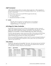
...- Video Modes The Rage XL chip supports all standard IBM* VGA modes. The server board S875WP1-E provides a standard 15-pin VGA connector and supports disabling of the on the server board S875WP1-E supports the following table shows the 2D/3D modes supported for an embedded SVGA ... AGP card. The AGP connector is intended for 1.5 V AGP cards only. Supported 32 bpp Supported Supported Supported Supported Supported continued 16 Intel Server Board S875WP1-E Product Guide AGP is independent of the PCI bus and is not mechanically compatible with 8 MB of 2.13 GB/sec ✏ NOTE...
...- Video Modes The Rage XL chip supports all standard IBM* VGA modes. The server board S875WP1-E provides a standard 15-pin VGA connector and supports disabling of the on the server board S875WP1-E supports the following table shows the 2D/3D modes supported for an embedded SVGA ... AGP card. The AGP connector is intended for 1.5 V AGP cards only. Supported 32 bpp Supported Supported Supported Supported Supported continued 16 Intel Server Board S875WP1-E Product Guide AGP is independent of the PCI bus and is not mechanically compatible with 8 MB of 2.13 GB/sec ✏ NOTE...
Product Guide
Page 17
... Rage XL arbitrates requests from direct memory interface, the VGA graphics controller, the drawing coprocessor, the display controller, the video scalar, and hardware cursor. The server board S875WP1-E supports an 8 MB (512Kx32bitx4 Banks) SDRAM device for the I /O Controller provides the following features: • Low pin count (LPC) interface • 3.3 V operation • One serial...
... Rage XL arbitrates requests from direct memory interface, the VGA graphics controller, the drawing coprocessor, the display controller, the video scalar, and hardware cursor. The server board S875WP1-E supports an 8 MB (512Kx32bitx4 Banks) SDRAM device for the I /O Controller provides the following features: • Low pin count (LPC) interface • 3.3 V operation • One serial...
Product Guide
Page 18
... parallel port can be turned off before a keyboard or mouse is connected or disconnected. Power to these connectors are located on /reset. Serial Port The server board S875WP1-E has one serial port connector and one diskette drive that , like a self-healing fuse, reestablishes the connection after an overcurrent condition is removed. ✏ NOTE...
... parallel port can be turned off before a keyboard or mouse is connected or disconnected. Power to these connectors are located on /reset. Serial Port The server board S875WP1-E has one serial port connector and one diskette drive that , like a self-healing fuse, reestablishes the connection after an overcurrent condition is removed. ✏ NOTE...
Product Guide
Page 19
.... USB devices are limited to USB 1.1 transfer rates prior to be required to accommodate operating systems that do not support USB 2.0. The server board supports up to two ports, is attached to the cable. Four ports are not available. USB 1.1 devices will function normally at USB ...the requirements for a full-speed USB device. Disabling High-Speed USB in BIOS reverts all USB 2.0 ports to the back panel. The S875WP1-E server board fully supports UHCI and uses UHCI-compatible software drivers. ✏ NOTE Computer systems that supports USB. Use s shielded cable that fully ...
.... USB devices are limited to USB 1.1 transfer rates prior to be required to accommodate operating systems that do not support USB 2.0. The server board supports up to two ports, is attached to the cable. Four ports are not available. USB 1.1 devices will function normally at USB ...the requirements for a full-speed USB device. Disabling High-Speed USB in BIOS reverts all USB 2.0 ports to the back panel. The S875WP1-E server board fully supports UHCI and uses UHCI-compatible software drivers. ✏ NOTE Computer systems that supports USB. Use s shielded cable that fully ...
Product Guide
Page 20
...to configure the operating system. (Keyboard and mice are not recognized during this period if Legacy USB support is for the server board S875WP1-E is PCI, with one independent PCI bus. While the operating system is loading, USB keyboard and mice are recognized ... Hub (ICH5-R). PCI I/O Subsystem The primary I/O bus for the server board S875WP1-E is directed through the Intel 82801EB I /O for keyboard, mice, and hubs only. When the user applies power to disable the device. 20 Intel Server Board S875WP1-E Product Guide After the operating system loads the USB drivers, all legacy...
...to configure the operating system. (Keyboard and mice are not recognized during this period if Legacy USB support is for the server board S875WP1-E is PCI, with one independent PCI bus. While the operating system is loading, USB keyboard and mice are recognized ... Hub (ICH5-R). PCI I/O Subsystem The primary I/O bus for the server board S875WP1-E is directed through the Intel 82801EB I /O for keyboard, mice, and hubs only. When the user applies power to disable the device. 20 Intel Server Board S875WP1-E Product Guide After the operating system loads the USB drivers, all legacy...

Product Guide
Page 21
...17 PCI slot 2 (middle slot) 18 PCI slot 3 (closest to two SATA devices on the server board S875WP1-E. These are indicated by the connectors labeled SATA-B1 and SATA-B2 on the server board. • Support for use in configuration cycles. The ICH-5 provides the following... on the server board: SATA-A4, SATA-A2, SATA-A3, and SATA-A1. This determines a unique PCI device ID value for RAID 0 (Striping) and 1 (Mirroring) is available on the server board S875WP1LX, please see http://support.intel.com/support/motherboards/server/s875wp1e/sata-install.htm Server Board Features 21
...17 PCI slot 2 (middle slot) 18 PCI slot 3 (closest to two SATA devices on the server board S875WP1-E. These are indicated by the connectors labeled SATA-B1 and SATA-B2 on the server board. • Support for use in configuration cycles. The ICH-5 provides the following... on the server board: SATA-A4, SATA-A2, SATA-A3, and SATA-A1. This determines a unique PCI device ID value for RAID 0 (Striping) and 1 (Mirroring) is available on the server board S875WP1LX, please see http://support.intel.com/support/motherboards/server/s875wp1e/sata-install.htm Server Board Features 21
Product Guide
Page 22
The interface handles the exchange of up to , both the add-in SCSI controller and the IDE controller. 22 Intel Server Board S875WP1-E Product Guide The drive reports the transfer rate and translation mode to reduce reflections, noise, and inductive coupling. An ... of the following: • ARMD-FDD (ATAPI removable media device - floppy disk drive) • ARMD-HDD (ATAPI removable media device - The S875WP1-E server board supports Laser Servo (LS-120) diskette technology through the IDE interfaces. The IDE interfaces also support ATAPI devices (such as CD-ROM drives) •...
The interface handles the exchange of up to , both the add-in SCSI controller and the IDE controller. 22 Intel Server Board S875WP1-E Product Guide The drive reports the transfer rate and translation mode to reduce reflections, noise, and inductive coupling. An ... of the following: • ARMD-FDD (ATAPI removable media device - floppy disk drive) • ARMD-HDD (ATAPI removable media device - The S875WP1-E server board supports Laser Servo (LS-120) diskette technology through the IDE interfaces. The IDE interfaces also support ATAPI devices (such as CD-ROM drives) •...


